I have been a member of St Paul's Church, Penketh, Warrington for many years. For all of that time the church has had an interesting organ to accompany singing. We believe it to have been made by Compton but it was extensively rebuilt by a local organ builder - the late Edward Ropson of Southport. While it has never been able to produce real pipe-organ sounds, it has been well use over the years and it well-loved by our organist. Since Edward Ropson died it has been maintained by his son David Ropson.
This year (2015) has seen the end of the present church building - the last service being held on the 11th of January. The building was intended as a temporary place of worship for the Penketh area, but has long outlived the original 10 year life expectancy. This year it is being demolished and a more permanent building will be constructed to replace it.
Initially the plan was to dispose of the organ and purchase a modern digital organ to replace it. However, I offered to convert it to a digital organ by removing the tone generators and valve amplifier and modifying the keyboards to generate MIDI signals. We could then purchase a MIDI sound module with pipe organ voicing and hopefully produce a more realistic pipe organ sound.
This was accepted with some enthusiasm, as the organ casing and keyboard are quite acceptable in appearance and behaviour. I have not guaranteed success in my efforts but will underwrite the initial conversion. If it proves to be a failure, then we can simply scrap the remains and revert to the original plan to purchase a new instrument.
With the closure of the church building following the final service on the 11th of January I have dismantled the organ. The parts to be modified have been removed to my workshop (after clearing a bit of workspace on my benches) and the wooden case of the organ is now light enough to be moved into storage for the duration of the rebuilding. While dismantling the instrument, involving a certain amount of experiment and a lot of unsoldering of wires, I took several photographs which I thought might be of interest:
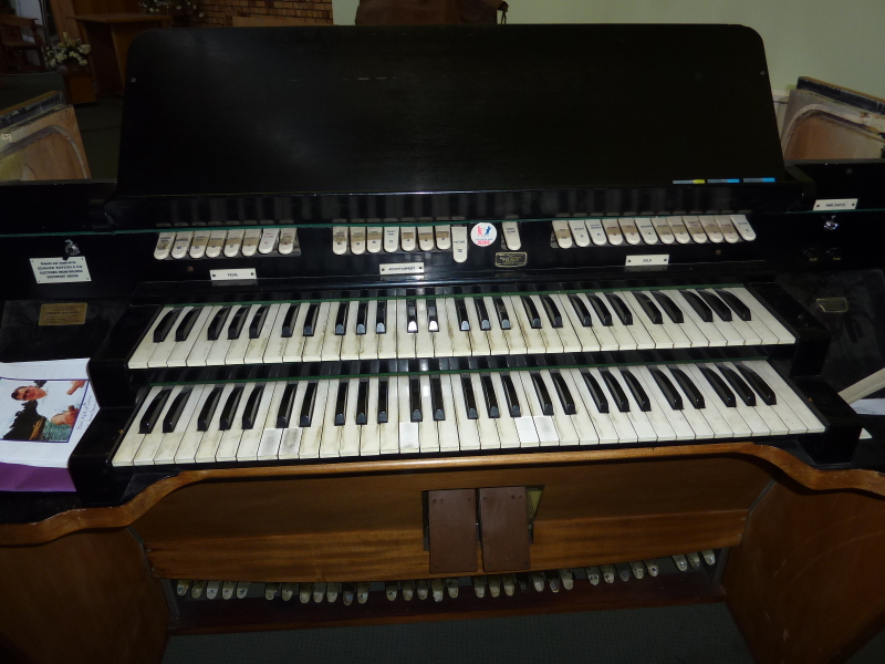
This is the organists view of the keyboards. It has two manuals and a pedal board. The pedals are easily removed, simply sliding away from the body of the organ. Adjustable projections on each pedal engage with the tabs seen at the bottom of the organ.
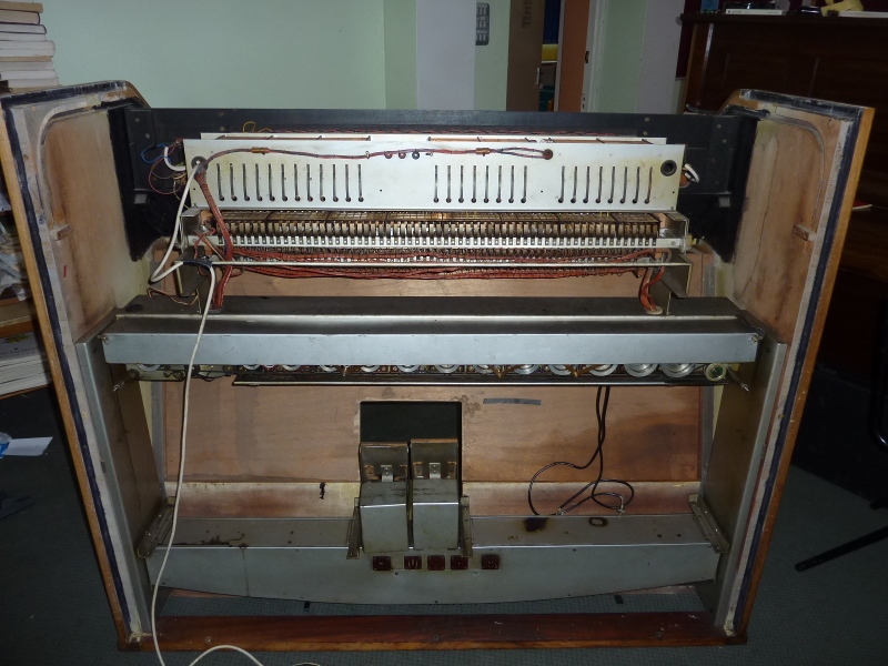
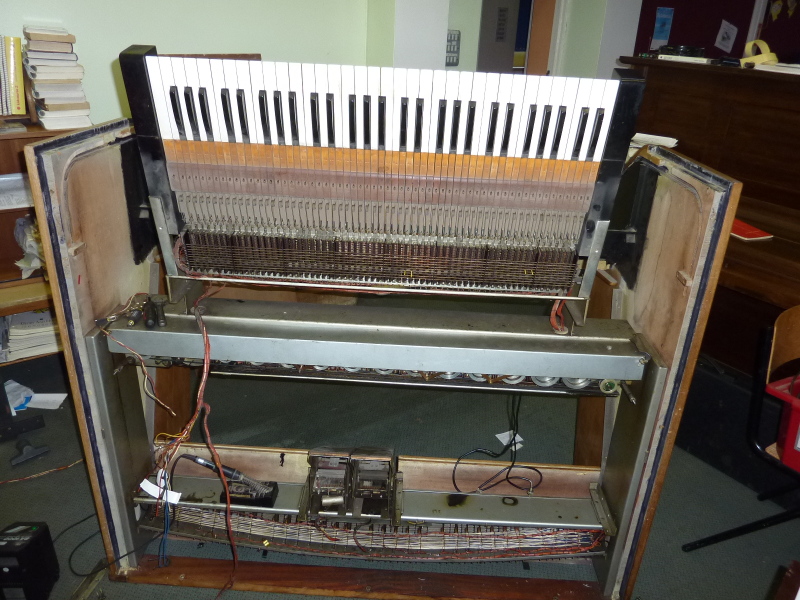
Here is a view of the back of the organ after the covering panels have been removed.
From the bottom up we have the pedal contact unit, which supports the two volume control pedals. This is supported by two steel side panels which also support the tone generator unit in the middle of the picture. This consists of two electric motors driving twelve rotors with electromagnetic pickups. These generate simple tone signals for each of the twelve notes in the scale. Each rotor generates a series of harmonics which are then added in varying proportions to simulate the organ sounds.
The tone generator unit in turn supports two brackets on which are mounted the two keyboard manuals and finally, at the top is the voicing unit which provides switching of the signals to produce the differing organ sounds.
The first unit to be removed, the voicing unit, was fairly straightforward to remove.
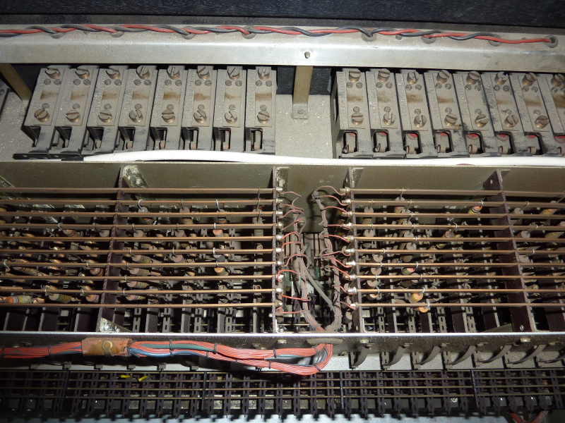
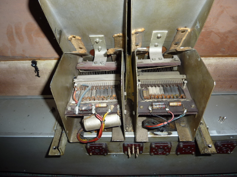
This is a close-up of the unit, showing two of the three sections. In this photo we have the voicing for the lower manual (left) and the pedals (right). This unit consists of a number of busses switched in by operation of tabs above the keyboard (see photo of keyboards above).
In order to remove the unit, it was necessary to unsolder the wiring cables which can be seen coming from the lower left and soldered to the ends of the busses.
Here we see the end of the voicing unit with the wires unsoldered but now yet withdrawn. Note the thicker yellow wire which has not yet been unsoldered. When I unsoldered the wires from the other two sections I found it impossible to get down to the corresponding wires there. At this point I decided I would need to turn the unit over to get at these wires and undid the bolts which held the unit down. I was a little surprised to find these bolts to be quite loose, but with lock nuts attached. Eventually I realised that these bolts are simply a hinge and the unit, complete with the front panel and tabs simply lifts up and back for access to the underside! I replaced the bolts (for the moment) and found that unsoldering the problem wires was now easy and the unit was then removed.
Having discovered the hinge, I then found it easy to list the upper manual which pivots on the same pair of bolts.
We now have the upper manual raised which is very convenient as it provides access to the underside of the keyboard:
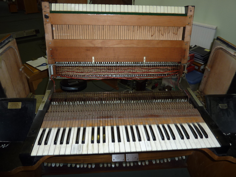
The underside of the keyboard is a mass of wiring. At this stage I was only concerned with separating the units for removal, so most of the wiring got left in place. There were, however, three cables of wiring to individual keys that had to be removed - about a hundred wires to be disconnected! Fortunately the individual wires are soldered to smooth pins and once the soldering iron was applied they simply slid off. I have yet to figure out, and probably never will, just how this wiring is organised. Some goes down to the tone generators and some to the voicing unit. As the wires are bundled tightly into cables it is possible that some goes to the other keyboard, but who knows!
Once the wires had been removed and the cable extracted through the gaps at the ends of the keyboards, it was easy to remove the unit.
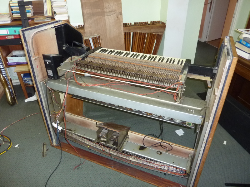
The upper manual has been removed and it remains to repeat the process with the lower manual.
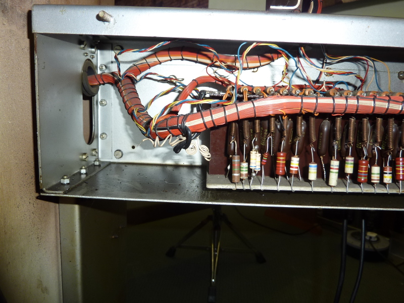
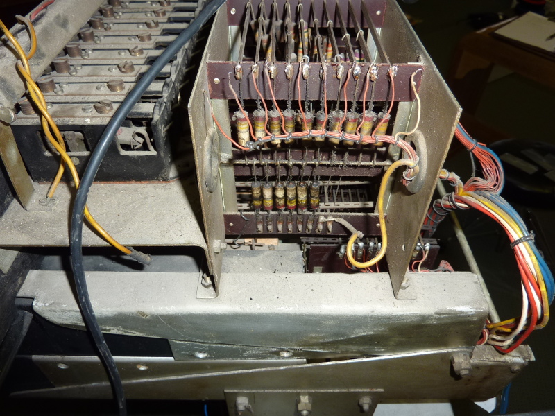
This photo shws the two cables, one coming down from the keyboards, and the other coming up from the pedal unit and entering at the left side. The cable runs up behind the side panels and is inaccessible until the frame is extracted from the organ case.
One interesting feature in this photo is the array of resistors going off to the right. These are not soldered in, but have been bent into hooks and attach at the lower end to a common bus bar and the upper end is caught in a hook. I understand that the organ maintainer adjusts the values on these to vary the tonality of the sounds produced. I would have thought it might be prone to oxidation of the contacts but that doesn't seem to be a problem.
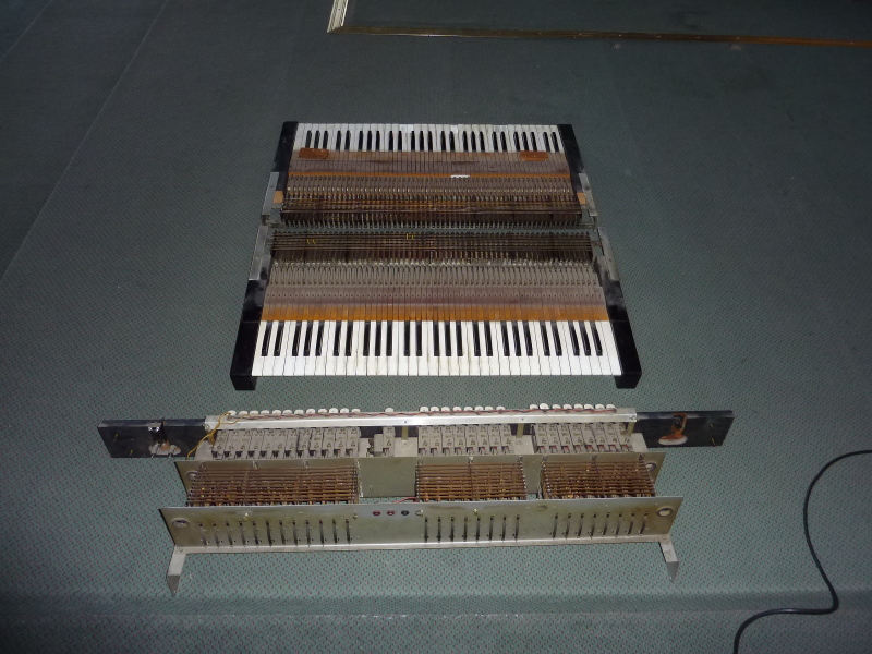
The three units removed from the organ: two keyboard manuals and the voicing unit.
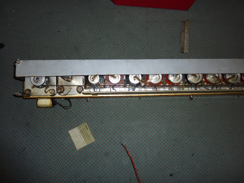
Here we have one end of the tone generator unit from the rear side. I should have taken the cover off before taking the photo, but didn't think of doing so at the time. You can see, from the left end, the pulley on the drive motor which spins the generators at constant speed. The speed of the motor will affect the pitch of the notes, so it must be a synchronous motor.
Next to it is a second motor. This gets switched in when then tremulant tab is operated. It drives an eccentric pulley which simply wobbles the drive belt, and hence varies the pitch slightly. A sping-loaded pulley at the other end of the unit takes up the slack and maintains an even pressure between the belt and the generator pulleys.
Following the motors we have the generator pulleys. These drive toothed wheels with electromagnetic pickups. Each of these generates a fundamental and harmonics for a not on the chromatic scale, so there are twelve along the unit. The various harmonics are added in suitable proportions controlled by the voicing units to produce the organ sounds.
This unit is not needed for the modified organ and we propose to offer it back to the firm that supplied the organ for use as spares. However, it does act as support for the keyboards, so we will have to replace it with something rigid. If the suppliers are not interested we will strip off the motors and generators and use it purely as a support.
Finally, for the moment, here is a photo of the volume pedals. These operate my pressing a slanting contact bar against a series of springy wires which are connected to resistors. In effect the are a variable resistor which act to reduce the level of the signal being fed into the amplifier.
One item of interest that I forgot to photograph is the amplifier and power supply. These are two very heavy chassis which unplug from the sockets on the pedal unit. The amplifier is in fact two amplifiers, one of which handles the lower notes and the other takes the higher notes. These each have a pair of KT66 valves driving the output and very substantial output transformers. The organ speakers are two large wooden cabinets with 15" bass units and 4 8" mid-range units. The latter are mounted on a windmill-type structure which rotates when the organ is switched on, giving something of a Leslie effect. There are no top-end tweeter elements. We propose to keep the speakers but will add suitable tweeter units. As the sound module will produce stereo outputs, we will have to decide whether to have separate low, middle and top amplifiers, and filter the signal before amplification or have a single pair of amplifiers with post-amplication filtering. As I am not an expert on audio systems, we will take advice on this!
Where do we go from here? At present the keyboard operates a number of contacts from each key. These are simply springy wires which are pushed via a slider strip to make contact with busbars running the length of the keyboard. This provide a number of make contacts for each key. We could use these directly to do the conversion, but the system is prone to contact bounce which could be a major problem. I will try experimenting with this to see if it is the case. If, as I suspect, this is a problem I have an idea for a better method, but which requires more work. The second approach involves making each key operate a single change-over contact, which means that the whole contact assembly will need to be replaced.
In order to generate MIDI signals, we need to detect when a key has been pressed and then released. To do this I propose to use an Arduino microcontroller on each keyboard (and the pedal unit). The controller will generate scanning signals which select small groups of notes and feed the pulses to the contacts. Those contacts which are operated will pass the signal back to inputs on the controller. By repeating this at high speed over the extent of the keyboard we can check the state. If the state has changed we can send out the appropriate signal. I have written an initial prototype program to do this and look forward to testing it out on the keyboards.
A further microcontroller will act as coordinator and take the individual note events and route then to the digital sound generator after applying various transformations, thus we can effect couplings and splits at this level.
If we have to go for the changeover contact arrangement, this will operate in the same way but instead of there being just tow states - connected and not connected - we have instead four states.
An interesting feature of this method is that it gives us an opportunity to determine the speed at which the key is pressed. By timing the transition from state 1 to state 3 we can produce a velocity signal for the MIDI generator. For purely organ sounds this will be ignored, but it could make it possible to use the organ for other sounds such as piano or brass instruments.
In conclusion, at this time the project is just beginning and much work needs to be done. Testing and deciding which way forward. We also need to look at the sound generating side of things. We need to find a good commercial sound generator which is capable fo producing a realistic pipe organ sound.
In due course I will revise this page to say how the work is developing.
Bill Purvis
16th January, 2016