The problem that has arisen is that the release ratchet is no longer firmly attached to the release shaft and can become displaced. If this happens, then the result is that the drum is released immediately and never moves beyond the first position.
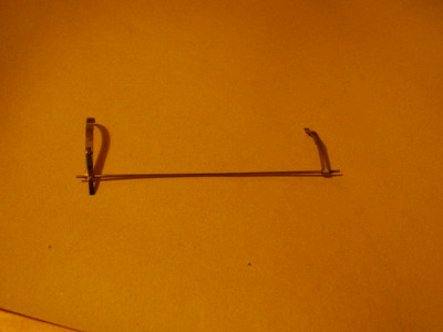
Photo of the release shaft. The release ratchet is the lever at the
right hand end of the shaft.
The main problem in fixing this is that the alignment of the release ratchet, relative to the release lever, is crucial. It is fairly easy to set this with the shaft in position, but the simplest method of fixing the ratchet to the shaft would be to use a modern engineering adhesive (Loctite). However, the problem is that Loctite hardens very quickly when the parts are placed in contact and it takes several minutes to re-install the shaft. By the time the shaft was in place the glue would have hardened enough to prevent the ratchet from being moved into the correct alignment.
My solution to this, after a couple of weeks mulling over the problem, was to make a small jig which could be clamped onto the shaft and provide a reference so that the ratchet could be glued, applied to the shaft and aligned within less than a minute.
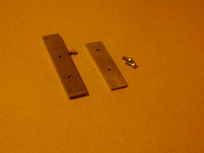
Parts of the jig - two plates, with a groove in the larger and
two screws to clamp them together over the shaft. A modified
screw (half the head removed) is fixed into the side of the
larger plate.
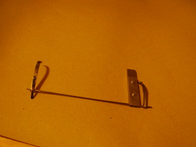
The jig clamped onto the shaft. This can be done with the shaft
installed and the ratchet aligned correctly. By carefully locating the
modified screw against the ratchet, the plate can then be clamped by
tightening the screws. The shaft can then be removed from the
machine so that the ratchet can be removed, glued and returned
against the locating screw. After a few minutes for the glue to
harden, the jig can be removed and the shaft re-installed. A couple
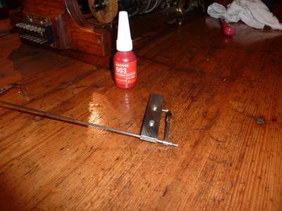
of very small flats should be made on the shaft to ensure that the
glue is not squeezed out of the joint - Loctite recommend 0.005"
clearance, but as this is not a high-torque situation, a couple
of small flats should provide enough area for the glue to create
a reasonable bond. If the ratchet ever needs to be removed a
little heat will break the bond and release it.
Page Created by Bill Purvis. Last update 24th October, 2010
Contact me at: bill 'at' billp.org
| You are visitor number 3199 |