During a maintenance session we noticed that one of the bells (Number 11) was not being rung when ringing rounds on 12 bells. After checking the cable from the machine to the bell cabinet to no effect, I tried prodding the wiring harness on the underside of the machine. This harness consists of 12 wires which connect the contacts on the distributor plate (#512) to a set of terminals on the inside of the rear end plate. These terminals are fixed to the brass strips that lead up the plate and make contact with the pins on the underside of the conductor plate (#805).
Prodding this harness had the desired effect - bell number 11 started ringing. However, it seems that the wiring has fractured and the contact is intermittent. The only reliable cure was to replace the wiring harness. Since the wiring is old it seemed to be prudent to replace all the wiring at the same time.
Rather than try to make up the cable in situ, I decided to construct a jig which would allow me to make up the harness at home so that it could easily be installed within a few minutes at Loughborough. In order to ensure that I got the right dimensions, I paid another visit to Loughborough (23rd July, 2010) and, amongst other things, I made carefull measurements of the existing harness.
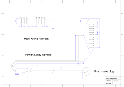
CAD schematic drawing of the wiring on the machine
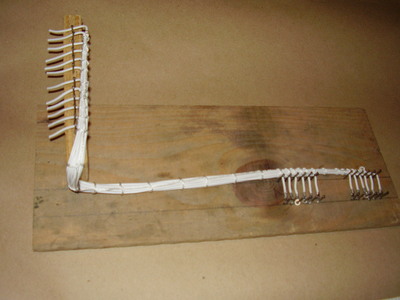
The jig was constructed from some scraps of wood from an old packing case. Not an elegant sight, but effective:
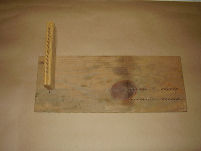
Overall view of the jig.
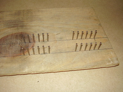
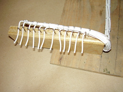
View of the distributor end of the jig.
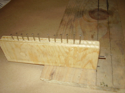
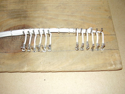
View of the terminal end of the jig.
The jig consists of two pieces of wood, a baseboard and a cross piece. The harness is a 3-D object and the terminal end is one inch lower than the distributor end. Two rows of panel pins were inserted into pre-drilled holes at the distributor end. One row acted in place of the screws to which the harness is attached, while the second row, spaced one inch away, is used to bend the wire through 90°. At the other end, a further pin acts to bend the harness upwards through 90°, then it bends another 90° over the top of the cross piece before a third row of pins are used to bend each wire out towards the terminals.
View of the jig with the harness in place.
View of the distributor end of the harness on the jig.
View of the terminal end of the harness on the jig.
Once the harness was laid out on the jig, a string cord was used
to lace up the harness and preserve its shape. When it was removed
from the jig, the tension in the lacing cord and the natural
tendency of the wires to curve distorts the shape of the harness
somewhat, but once in place I am sure that it will be OK.
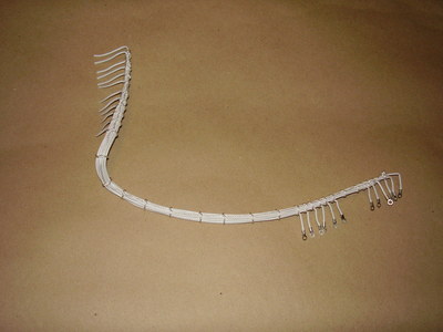
The almost completed harness after being removed from the jig.
It only remains to strip back the wires at the terminal end
for 0.25" and tin the ends.
The power lead was next to be tackled. This is a length of cotton covered three-core flex in what is now described as Burgundy colour. This is obtainable for period light fittings etc. but at a price. I had to order a length, and pay in advance as the shop was convinced that if they ordered it and I didn't come to collect and pay, then they'd be stuck with it forever!
The power cable conveys 24V DC from the power unit in the base box to the machine. The connection is by means of a 3-pin plug - one of the old 2-Amp rated round-pin plugs. Fortunately these are still available (to my surprise) and a few days after I acquired a couple from a friends junk-box I saw a table lamp fitted with one of these in a pub!
The original cable has the outer covering stripped off inside the machine and the end of covering is whipped to prevent fraying. I plan to use heat-shrink tubing instead - the replacement is not that authentic and the tubing will be out of sight under the machine.
No photos of this cable yet as I've not made it up yet!
This is a straightforward mains flex - I use the remaining Burgundy fabric-covered flex for this. A standard 13-Amp plug is at the end.
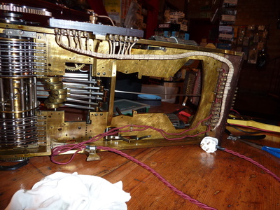
This photo shows the underside of the machine with the new power lead installed. The burgundy-coloured leads along the bottom are the ones in question.
The white harness of wires is the original
signal wiring which was next replaced.
This photo shows the ends of the harness where it connects to the distributor panel. The 6BA screws which form the connection can be clearly seen here. I wish that I had brought my set of small spanners, as I had to use a pair of long-nosed pliers to undo and re-tighten the nuts. This took far too long!
Once the wiring was back in place I ran a short test to ensure that the new wiring was correct. The machine was set to ring rounds and this was fine apart from bell number 10, which was silent! This was eventually tracked down to a dirty contact on the bell-plate. Once that was cleaned, all 12 bells rang satisfactorily.
Page Created by Bill Purvis. Last update 12th October, 2010
Contact me at: bill 'at' billp.org
| You are visitor number 3926 |