
This Report describes the purpose and construction of the EDSAC (Electronic Delay Storage Automatic Calculator) as it exists either as actual equipment or in the design stage, at the time of writing (May 1948).
The Report is intended only for use within the Mathematical Laboratory, and is in no sense a publication of the Laboratory. It will no doubt require modification from time to time as the construction of the machine proceeds, and components which have not been fully constructed or designed are described only in general principle.
[Editor's note: This document has been transcribed from scanned copies of the original documents. The layout has been adapted somewhat for web display, but every effort has been made to ensure that the sense of the original document has been preserved. If there are any remaining typos or other errors, I would be happy to receive notification and would undertake to correct them as soon as possible.
A further note: the scanned copies had a number of pencilled amendments which I have incorporated into this document where they are in agreement with known facts. ]
THE EDSAC
The application of electronic devices to computing machines and instruments is already widely established, but it is generally accepted that the term 'electronic' machine should be applied only to those which use electronic means to carry out the actual mathematical functions, rather than simply to control the operation of realys or counters. At the present time (May 1948), one electronic machine only – the ENIAC, at the Moore School of Electrical Engineering in Pennsylvania – is known to be in full operation, although a number of others are projected, or are under construction.
The ENIAC fulfils satisfactorily the purpose for which it was designed, but its limitations for general computing work have resulted in a modified approach to the design of further machines. In particular, there has been a marked trend towards (a) a larger memory capacity, and (b) the use of the binary, rather than the decimal, scale for computing processes. An increased memory capacity will obviously lead to greater flexibility and scope. The use of the binary scale has certain advantages which result from the fact that electric or electronic citcuits can deal more readily with a variable which has only two stable states than with one which has ten.
A number of electronic binary digital machines are being developed in the U.S.A, in Great Britain and elsewhere. This report deals only with the machine known as the EDSAC (Electronic Delay Storage Automatic Calculator), which is under construction in the Mathematical Laboratory of the University of Cambridge, and no attempt is made to compare the methods and devices used in the EDSAC with those used in other machines.
The EDSAC will have initially a memory capacity equivalent to that required for 512 ten-decimal numbers (i.e. numbers comprising 34 binary digits). The numbers or orders will be represented by trains of electrical pulses, each pulse lasting approximately 0.9 μsec, the repetition frequency being 500 kc/s. Each pulse has an approximately square wave form, the amplitude being of the order of 18 volts. The presence or absence of a pulse will represent respectively the digit 1 or 0. Althought the machine will carry out all internal operations in the binary scale, conversions from the decimal to the binary scale, or vice versa, will take place in the machine, so that, from the point of view of the operator, the use of the binary scale need not be taken as a serious limitation to its conveniencec of operation.
To facilitate a description of the machine, it is desirable to consider first the ways
in which number will be represented, stored and transferred from one storage device to another.
2. Representation of numbers and orders.
In general, every number or order is represented by a train of pulses, and order occupying 18 pulse intervals, and a number either 18 or 36 pulse intervals, according to whether the number is of five or ten decimal digits. The period occupied by a ten-digit number (i.e., 36 pulse intervals) is known as a 'minor cycle' (M/C), the length of which is approximately 72 μsec. The digits are represented in succession, starting from the least significant, i.e. the right-hand digit, and are followed by a 'sign' digit and a blank. The sign digit is 0 for a positive number and 1 for a negative number.
Numbers containing ten and five decimal digits will be referred to as 'long' and 'short' numbers, respectively.
The position of the binary point is between the sign digit and the highest significant digit (i.e. between the 35th and 34th digit position for a long number, and between the 17th and 16th digit position for a short number).
Negative numbers are represented as complements, a unit sign digit indicating that the quantity -1, to which the remainder of the number is added.
It should be noted that it is common practice in some centres to represent a binary number on paper with the least significant figure on the left. However, the convention adopted in relation to the EDSAC is similar to that used in ordinary decimal notation. The left-hand digit denotes the sign, the next is the most significant digit, followed by the remaining digits in descending order of significance. Thus:
01101 represents + (1 + 2-1 + 2-3)
and 1101101 represents -2 + (1 + 2-2 + 2-3 + 2-5).
[ed: the above conforms to the original format, with decimal point between the 34th and 33rd binary digits, I have taken hand-written amendments to the text as valid.]
A binary point may be inserted after the first digit, but it is not represented physically in a pulse train.
It is clear from the above that every number, n, represented in the machine must be such that -1 ≤ n < 1.
[ed: hand-written text was -1 ≤ n < 2, but this cannot be correct.]
It is important to note that in forming a complement, all digits, starting from the right are identical with those in the original number up to and including the first '1'. The remaining digits, including the sign digit, are reversed.
For example:
| Original number: | 01.1001 1000 |
| Complement: | 10.0110 1000 |
Precautions are taken to see that in processes such as addition, the binary points are properly aligned.
The pulses contained in a minor cycle are designated P0, P1, P2,...... P35. The digits of a long number are represented by the pulses P1 to P34, P35 being the sign digit and P0 a blank. A short number may occupy either the first or second half of a minor cycle, and is represented by either P1 to P16, sign digit P17, (P0 blank), or P19 to P34, sign digit P35, (P18 blank).
A system similar to that used for representing numbers is also used for orders. An order occupies a half minor cycle and is normally in two parts, the first, or numerical, part representing a 'memory position' and the second, or operative, part repressenting the nature of the order, suitably coded.
A single train of pulses, as described above, provides a transient representation of a number or order, and is useful only in performing a single operation, such as a transfer from one position to another. In general, however, it is necessary to retain numbers or orders in the machine, either for the short time required to allow a single mathematical operation to be completed, or for a longer time when the number is required at various stages in the solution of a problem. Provision must be made for the temporary retention of an order in static form whilst it is being carried out. To meet the former requirement a 'memory unit' is required, which will enable the number, in pulse form, to be repeated at regular intervals, and so to be available for use at any time. The retention of orders in static form is accomplished by 'flashing units' which translate the train of pulses representing the order into a temporary form which enables the order to be carried out.
Experience has shown that the memory unit is of such fundamental importance that it must be considered as the basic unit on which the whole design of the machine depends. It is therefore desirable to describe the operation of the Memory before proceeding to a general description of the machine as a whole.
Various types of memory unit have been described elsewhere, and include those depending on electrostatic, ultrasonic, magnetic or other phenomena. The memory unit used in the EDSAC consist of a number of ultrasonic delay tanks, and has recently been described in detail. 1
Superficially, each tank consists of a mercury-filled steel tube of 1 inch external diameter, lying horizontally between two end blocks approximately 5 ft. 4 in. apart. The tanks are arranged in 'batteries', each containing sixteen tanks.
A large memory capacity is desirable, and the EDSAC will have initial capacity for 512 long numbers. In order to avoid an excessive number of tanks with their associated control gear, each memory tank is designed to deal with 16 numbers, and thus 32 tanks are required.
The requirement for each tank is to admit in succession 16 pulse trains, each of one minor cycle duration, and to provide for their constant repetition in sequence. Thus the tank must provide an output, identical in form with the input, but delayed by 16 M/C (i.e. about 1.15 millisec.), the output being fed back into the input to initiate the next series of pulse trains.
In principle the tank is essentially a pulse delay unit which provides a delay of exactly 16 M/C to each pulse received and then returns it to the input of the tank for further circulation. Each tank thus provides a self-contained system in which a series of pulses, having once been introduced from an external source, will continue to circulate with a repetition frequency of about 870 c/s, one complete cycle of operation being known as a 'major cycle' and containing 16 x 36 (= 576) pulse intervals, or 16 minor cycles. The major cycle is illustrated diagramatically in Fig. 1.
The memory tank takes the form of a tube of mercury terminated at each end by a piezo-electric crystal. Each incoming pulse is used to modulate a carrier wave of frequency 13.5 Mc/s, and the modulated signal is thus converted into a mechanical pulse of ultrasonic frequency, which travels to the other end of the tank, where the receiving crystal converts it again into an electrical pulse. The length of the tank is designed to provide a delay of exactly one major cycle.
In order to avoid the progressive distortion in wave-form which would occur due to successive passages through the tank, a special device is used to 'rejuvenate' the pulse after each passage. This device makes use of 'clock pulses', which are the basic timing pulses for the whole machine.
Clock pulses are simply a succession of digit pulses at regular intervals of 2 μsec., and are used as a master timing device. The mercury-filled tanks have an appreciable temperature coefficient of velocity, and thus of delay, and it is of course essential that the timing of pulses should be uniform throughout the machine. This could be achieved by ensuring a uniform and constant temperature in all tanks, but it is sufficient if the temperature of all tanks is equal – not necessarily constant – if the repetition frequency of the clock pulse generator is also controlled by a tank at the same temperature. This is the method to be adopted, and will ensure uniformity of pulses throughout, even though their frequency may vary appreciably from time to time. It is therefore customary to discuss the timing of events in terms of major or minor cycles, or pulse intervals, rather than in terms of milliseconds or microsecond.
The outcoming pulse from the tank is not fed directly back to the input, but, instead, is used to 'gate' an undistorted clock pulse. Thus the input pulses to the tank are always undistorted, and the only distortion in the output pulse is that due to a single passage through the tank. It should be noted that in addition to limiting distortion, this device also limits any progressive drift in the timing of pulses. It is therefore used in various parts of the machine where time lags are likely to appear in electronic circuits, and where it is necessary to 'tidy up' the output pulses.
The 32 tanks are assembled in 'batteries' of 16, and each tank has associated with it a control panel 1/, which, in addition to provision for input and output, contains also the terminals necessary for input, output and 'clear' gating waveforms.
The transfer of a number from Memory is carried out by applying a suitable gating e.m.f. to the output gate. This does not, however, remove the number from the tank, where it remains in circulation until another number is required to replace it. In this case, the new number is admitted through the input gate, and the clear gate is closed for the corresponding interval to inhibit circulation of the original number.
For the transfer of data from one position to another two 'buses' are provided. These are known as the 'Main Input Bus' and 'Main Output Bus', and provide routes to and from various components of the machine. The actual transfer of the data is controlled by gates in the respective components, and takes place according to the orders stored in the machine.
Since each memory tank contains the information stored in 16 minor cycles, the transfer of a number involves the selection not only of a route ( by means of gates ), but also of the actual M/C of [ed: or?] half M/C within the major cycle stored in the particular memory tank. Thus the operation of gates must be controlled not only in a geographical sense, but also precisely in time. This operation is thus analogous to that of a stroboscope, except that it occurs once only for any particular transfer. It is carried out by means of a 'Coincidence Unit'.
Apart from the 16 M/C delay tank used in the Memory, delay tanks of various lengths are used for temporary storage and for other purposes elsewhere in the machine.
Mention was made earlier of the need for static storage of orders, as opposed to dynamic storage which is achieved by circulation through the delay tanks. Static storage is required, for example, to enable a route to kept open, by means of gates, during the process of 'finding' a number in a memory tank and transferring it to another part of the machine. The 'Flashing Unit', which achieves this purpose, consists of a series of 'flip-flop' circuits, so arranged that when actuated by a train of pulses, they will assume an electrical configuration such that each flip-flop, bit 'on' or 'off' state, will represent one digiti of the order, and will maintain its state for sufficient time for the order to be carried out. The flashing unit is normally reset automatically before each operation.
The above description is sufficient to enable the general method of operation of the machine to be understood. A more detailed description of the memory and storage devices will be given later.
The Input section consists of two parts – the Tape Input and the Initial Input.
The Tape Input provides a means for introducing into the Memory the whole of the instructions and numerical data required for the solution of a problem. These data are prepared in the form of punched tape, and the operation of punching the tape can be regarded as a physical interpretation of the 'programming' of the problem, and thus represents the stage where human planning gives place to purely automatic physical operations. From this stage onwards, the machine operates automatically and presents the solution on punched tape or in printed form. It should be noted that the act of punching numerical data on the input is done in decimal notation and the output may be similarly presented.
In the sequence of operations associated with the input of data to Memory, all numbers are converted from decimal too binary form. The whole of the sequence of input operations may take place before the solution of the problem proceeds, or may, by suitable programming, occur at various stages of the solution.
The transfer of orders from Input to Memory is in itself a series of operations which requires the existence of orders in Memory to allow it to take place. These initial orders may be applied by some form of mechanical switching, and a number of banks of uniselectors provide a very suitable method. However, the number of operations involved is rather large and would be require an excessive number of contacts in the uniselectors if the whole process were to be carried out by this method. It is more convenient to use the normal processes of the machine as far as possible in the initial transfer of orders to Memory.
Provision is therefore made for this initial transfer to be carried out in two stages. The first is the transfer of a set of standard orders, known as initial input orders, to Memory, by means of uniselectors and associated equipment, known as the 'Initial Input'. These orders enable the machine, through its normal processes, to transfer to Memory from the input tape a standard series of 'synthesis orders', which provides for the remainder of the input process to be carried out.
Although the initial input and synthesis orders are normally of standard form, the occasion may arise for variation of the synthesis orders to suit a particular problem. This may be left to the discretion of the programmer, who may prefer to punch a special series of synthesis orders on the input tape, rather than use the standard set of synthesis orders.
At this stage, the description will be helped by an outline of the types of order with which the machine will deal. They are designated by symbols, which normally comprise a numerical and an operational part. The numerical part usually indicates a position in Memory, which is coded in the following way.
Order pulses are designated On, the pulses O1 to O12 comprising the numerical part, and thus serving to indicate:
The pulse O1, if present, denotes a long number.
The pulse O2, if present, denotes the second half M/C.
If absent, it denotes the first half M/C.
The pulses O3 to O6 specify the M/C, in binary notation.
The pulses O7 to O11 specify the tank number in binary notation.
The pulse O12 is a spare.
The pulses O13 to O17 form the operational part of the order.
The coding of this part is quite arbitrary within certain broad limitations, and at the time of writing, the code has not yet been specified. The types of order are as follows:
| A(n) | = | Add. Transfer number from Memory position n, and add into Accumulator. (The Accumulator is a tank which contains the result of operations in the Computer). | |||
| S(n) | = | Subtract. Transfer number from position n, and subtract from total in Accumulator. | |||
| M(n) | = | Prelude to multiplication or collation. Transfer from position n to Multiplier Tank in Computer. | |||
| C(m) | = | Collate. To collate is to multiply the corresponding digits of two numbers, e.g.
C(m) is the order to collate the number in Memory position m with the number already in the Multiplier Tank, and add the result into the Accumulator. | |||
| N(m) | = | Multiply. Multiply the number in position m by the number in the Multiplier Tank and add product into the Accumulator. | |||
| N'(m) | = | as in N(m), but subtract from total in Accumulator. | |||
| T(n) | = | Transfer from Accumulator to Memory position n, and clear Accumulator. | |||
| T'(n) | = | As in T(n), without clearing Accumulator. | |||
| I(n) | = | Input. Read next row of holes on Input Tape and put result in Memory position n. | |||
| O(n) | = | Output. Punch first 4 binary digits of number in position n, on Output Tape. | |||
| D(n) | = | Conditional Transfer Order (C.T.O.). Examine sign of number in Accumulator. If negative, carry on with orders in normal sequence. If positive or zero, transfer control to that specified in Memory position n. | |||
| R(n) | = | Right Shift. Shift contents of Accumulator n places to right (1 ≤ n ≤ 10). | |||
| L(n) | = | Left Shift. As in R(n). | |||
| Z(1) | = | Round off number in Accumulator to 34 binary digits (i.e. add 1 to 35th digit). | |||
| Z(2) | = | Round off number in Accumulator to 16 binary digits. | |||
| Z(3) | = | Stop machine and ring alarm bell. |
The coding of orders is arbitrary, within the limits of standard teleprinter tape, which provides for five holes (or spaces) abreast. A hole and a space represent the digits 1 and 0 respectively. Use is not made of the combinations 11111 and 00000, the former being reserved for overprinting errors, while the latter is indistinguishable from blank tape. Orders are transferred to memory in groups of four or five digits at a time.
In the case of numbers, the coding occurs in two stages. The first stage takes place in the punching of the tape, in which decimal notation is automatically transferred to coded decimal notation. Each row of holes represents a decimal digit of the number, expressed in binary form, thus requiring only four of the five possible positions. The digits (i.e. rows of holes) are then transferred, in descending order of significance, to the least significant places in the required memory position. Before each successive addition of a decimal digit, the total already in the Accumulator is shifted three places to the left to make room for the incoming digit. This is equivalent to multiplying the total by 8, whereas the factor should be 10. Thus, before making the shift, the total already in the Memory position must be multiplied by 1.25, which, in binary notation, is 01.01. For example, if the number, expressed in decimal notation, is a0, a1, a2..........a9, its true value is a0 + a1 x 10-1 + a2 x 10-2 +......+ a9 x 10-9. The digit a0 is first placed in coded decimal form, in the four lowest positions in the Memory position, so that it appears in Memory as a0 x 2-33.
When multiplied by 01.01, and shifted three places to the left it becomes a0 x 10 x 2-33, expressed in full binary form. When this process has been carried out ten times, the value of this digit in Memory becomes a0 x 1010 x 2-33.
Similarly, the digit a1 alone, shifted nine times, would appear as a1 x 109 x 2-33. Thus, when the whole number has been transferred, the total in the Memory position will be:
1010 x 2-33 (a0 + a1 x 10-1 + a2 x 10-2 + .......+ a9 x 10-9).
This total is then multiplied by 10-10 x 233, and the product will represent the input number in true binary form. The multipliers used during the coding process, namely 10 x 2-3 and 10-10 x 233, are respectively 1.25 and approximately 0.86. They therefore comply with the requirement that all numbers used in the machine must be less than 2, but the need for the multiplier 0.86 requires that no number numerically greater than 1.72 may be transferred from Input to Memory, since otherwise, the Accumulator would become overloaded before the final multiplication takes place.
A similar process takes place in the case of a short number, with appropriate modifications in detail.
The Control Section is the group of components which control the sequence of operations of the machine and provide the detailed 'instructions' for carrying them out. In particular, it normally subdivides each operation into two stages, as follows:
Stage I involves the determination of the next order in the computing sequence, the extraction of that order from Memory and its temporary storage in a decoded form – i.e. the form in which the carrying out of the order will automatically follow the extraction from Memory (or elsewhere) of the number on which it is to operate.
Stage II involves the extraction of the number converned and the completion of the sequence of operations prepared for it in Stage I. This is followed by the emission of an 'end pulse', or its equivalent, which initiates Stage I of the next sequence, and so on.
Although the Control Section initiates and controls the various numerical operations, the actual timing of the operations is regulated by clock pulses, or by pulses directly synchronized with them. In this sense, the Control Section may perhaps be best regarded as a preselector which controls the passage of pulses between various parts of the machine.
In addition to clock pulses, which are emitted regularly at approximately 2 μsec. intervals, a series of 'digit pulses' is also available, each digit pulse being repeated every minor cycle at the same position in the cycle. They are designated Dn, where n specifies the number of the pulse in the M/C. Fig 2 illustrates the timing of the D pulses.
The various sequences of operations will be described in relation to block schematic diagrams, in which the following colour code will be used where required:
| Green | = | Number or order pulse train. |
| Blue | = | Periodic pulses (e.g. clock, digit, M/C). |
| Violet | = | Timing pulses, not periodic (e.g. end pulses, etc.) |
| Black | = | Negative going D.C. potential (e.g. gating wave-form.) |
| Red | = | Positive going D.C. potential. |
The principal components of the Control Section are as follows:
In Fig. 3, which illustrates the components of the Control Section, the interconnecting lines are schematic and are intended only to indicate the relation between units. The colour code is accordingly omitted.
The M.C.U. is stimulated by either:
On receipt of one or other of these pulses, the M.C.U. initiates Stage I of the next order. This involves 'finding' the order in Memory, and for this purpose, it emits a gating e.m.f., which connects the Sequence Control Tank to certain Flashing Units and to the Coincidence Unit.
The S.C.T. is essentially a device for counting operations, and therefore stores the Memory position of the next order to be carried out, since the orders are normally held in successive positions in Memory, with certain exceptions which will appear later. The Tank Number Flashing Unit selects and provides a route to the appropriate tank, while the C.U. serves to select the precise position in that tank. In this respect, 'position' must be interpreted as position in a time scale – a 'Memory position' is specified by the number of the tank together with the 'position' in the tank, since each tank contains in circulation the contents of 16 minor cycles. The 'Counter Tank' with its 'half-adder' simply serves to count minor cycles, the five least significant digits being sufficient to specify any particular minor cycle within the major cycle of the Memory tanks. The half-adder is used to add one to the number in the Counter Tank at the beginning of each M/C.
As soon as the C.U. receives a stimulating pulse from the M.C.U., it is ready to 'seek coincidence'. This means that as soon as the number represented by D2 to D6 in the Counter Tank reaches equality with the appropriate digits (specifying the M/C) in the S.C.T., the C.U. emits a coincidence gating e.m.f., which opens the route from Memory to the Order Tank, to which the required order is transferred.
As soon as the order has been brought from Memory, it is possible to initiate Stage II, namely the carrying out of the order. The functions of the Supervisory Control in Stage II are essentially the same as in Stage I, but are modified according to the nature of the order obtained in Stage I. For example, the order may not involve the finding of a number in Memory, in which case the establishment of Coincidence is not required. If, however, the order includes a Memory position, the part of O2 to O6 is stored in the Order Tank, which plays the same part in establishing coincidence as the Sequence Control Tank plays in Stage I. Attention will be paid later to the variations in the procedure for Stage II, according to the type of order to be carried out.
The carrying out of an order normally involves the transfer of a number from a given Memory position, which involves the selection of a given minor cycle in a particular tank. It is therefore necessary to store the order in dynamic form, so as to provide the necessary data to the Coincidence Unit. This storage is provided by the 'Order Tank', which is similar in principle to a Memory Tank, but has a shorter mercury column, providing only a half minor cycle delay. Thus the order circulates twice every minor cycle, and is readily available for the establishment of coincidence.
However, the dynamic storage of an order is in itself insufficient, since the operational part of the order must be able to hold open the various routes (to the specified Memory tank, etc.) for the indefinite period, up to one major cycle, required to establish coincidence. The order must therefore be stored statically as well as dynamically. This is achieved by means of flashing units. The operational part of the order is stored in the Order Flashing Unit, and the numerical part (Memory position) is stored in the Tank Number and Half-cycle Flashing Units.
A flashing unit comprises a series of flip-flop circuits, each of which may be regarded as having two stable states, at least for sufficient time for their function to be carried out. When actuated by a train of pulses representing an order, or part of an order, each flipflop takes up one or other of its stable states, to represent the appropriate digit in the order. The condition of the flip-flops indicates a route appropriate to the particular order. For example, the Tank Number Flashing Unit indicates the number of the tank designated in the order to which it is required to provide a circuit in order to carry out the order.
The routes indicated by the flashing units are provided by means of 'decoders', which when actuated by the flip-flops, provide gating e.m.fs. where required to allow pulse trains to pass as required.
In the case of the Tank Number Decoder, the routing is quite straightforward, since the tank numbers are coded in binary form. However, the carrying out of an order involves a number of alternative routes, depending on the nature of the order, and a unit known as the 'Order Coder' is required to interpret the binary data set up in the Order Decoder as an actual route.
A long number occupies a fixed place in a minor cycle, and the binary point is thus in a fixed position, so that operations such addition can be carried out directly. However, a short number may occupy the first or second half of a M/C, and in the former case, the binary point occurs between pulses P15 and P16, whilst in the latter, and in a long number, it occurs between P33 & P34. Thus if the number appears in the first half of a M/C, it must be shifted one half M/C to the left before any arithmetical operation is carried out.
Conversely, if a short number resulting from an arithmetical operation (and therefore with its binary point properly aligned) is to be stored in the first half M/C of a Memory position, it must be shifted one half M/C to the right before storage.
A similar shift is required when transferring an order to the first half M/C of a Memory position.
The appropriate shifts are achieved by the 'Transfer Unit', which contains a half minor cycle delay tank, together with gates controlled by the 'Half-cycle Flashing Unit'. The latter unit stores, in static form, the order data specifying the position in the M/C, viz. O1 (long or short number), and O2 (first or second half M/C). The Half-cycle Flashing Unit is also required to provide the data necessary for the Coincidence Unit to establish coincidence when transferring a number to or from Memory.
Although the Conditional Transfer cannot be regarded in any sense as a unit of the machine, it is so important a function in the operation of the machine that it merits a general description at this stage. The conditional transfer order is used to allow the machine to determine whether a pre-determined condition has been met, and if so, to change to a new, pre-determined sequence of operations. In particular, the order D(n) requires that the machine should carry on with the carrying out of orders in sequence if the number contained in the Accumulator is negative, but that, if it is positive or zero, the next order should come from memory position n. Provision is made also for the use of the order D'(n), which operates in a similar manner, but with a positive total in the Accumulator as the criterion for carrying on in sequence.
In carrying out repetitive sequences, it is useful to note that the numerical part of an order may be subjected to arithmetical operations. For example, the first sequence may include an order relating to memory position k, but the following sequences may require the same order to be applied successively to the numbers in positions (k + 1), (k + 2), etc. This may be achieved by including, at the appropriate time in each sequence, the addition of 1 to the particular order, so that the order stored in one memory position will suffice to deal with a succession of numbers in different memory positions.
The Computer is the section where the basic arithmetical operations are carried out. These include addition, complementing, collation, multiplication and shifting. The whole section is controlled by the Computer Control Unit. Subtraction is achieved by complementing and adding. There is no provision at present for division, which can usually be avoided by proper programming, but it is possible that a dividing unit will be provided in due course.
The results of operations are stored in the 'Accumulator', which consists of two tanks of nearly 2 M/C total delay. Since numbers, each numerically less than 2, may be added successively into the Accumulator, it is possible, without proper programming, to overload the Accumulator – i.e. to bring the number in it beyond the limits ± 2. To show when this has occurred, an additional sign digit, identical with and adjoining the normal sign digit, is included with every number added into the Accumulator. The total in the Accumulator will therefore also have an additional sign digit at P0, and it is easily shown that the two sign digits will be identical only if the number n in the Accumulator is such that -2 ≤ n < 2. The two sign digits will be different if these limits have been exceeded, and the machine is automatically stopped and an alarm given.
The following example illustrates this point.
| Sign digits | binary point | ||||
| No. in Accumulator | 00 | 1 | 01101 | = | 1.40625 |
| No. added to Accumulator | 00 | 0 | 11110 | = | 0.9375 |
| True total | 1 | 0 | 01011 | > 2 | |
| Total shown in Accumulator | 01 | 0 | 01011 | ||
The Accumulator has a delay of 68 pulse intervals (i.e. 2M/C – 4 pulse intervals). A further delay of 4 pulse intervals is introduced in the circuits associated with the Accumulator tank, making a total delay of 2 M/C. These circuits comprise two half-adders (to be described later), the 'Accumulator Shifting Unit' (A.S.U.) and the 'Complementer-Collater'. The A.S.U. introduces normally a delay of two pulse intervals, which may be altered either to 1 or 3, as a means of achieving a right or left shift, respectively, of one pulse interval every 2 M/C, i.e. a shift of one digit for each circulation of the number in the Accumulator.
The Accumulator, Adder ( = two half-adders) and A.S.U. form a closed circulation system. Addition is carried out by introducing the addend, as a train of pulses into the Adder. The Adder operates in the following way.
The half-adder shown schematically in Fig. 4(a) comprises an electronic circuit, which receives simultaneously two trains of pulses. Its output also consists of two trains of pulses, such that one of the output trains represents the sum of individual digits in the numbers represented by the input trains, neglecting the 'carry' digit, while the other output train represents the carry. The relation between input and output is shown in the following table, in which the digits 1 and 0 represent the presence or absence of a pulse, respectively.
| INPUT | OUTPUT | ||
| A | B | 'Sum' | 'Carry' |
| 0 | 0 | 0 | 0 |
| 1 | 0 | 1 | 0 |
| 0 | 1 | 1 | 0 |
| 1 | 1 | 0 | 1 |
If a 'carry' pulse, when present, is delayed by one pulse interval and fed back into one of the inputs, for example, input B, it will clearly be added in the correct place for carrying out an addition. However, the delayed pulse may coincide with a pulse in B, in which case it will be neglected, since the Adder cannot distinguish between a single pulse and two pulses from different sources in the one input. Thus the simple half-adder shown in Fig. 4(a), can only add correctly provided that it is impossible for a delayed pulse in the feedback to coincide with a pulse in input B. This condition is met when the input B is a pulse in the least significant place only, and thus the half-adder may be used as a counter of events which cannot occur twice within the delay time of the associated tank. Thus, half-adders are used in conjunction with the Sequence Control Tank and Counter Tank in the Control Section ( see § 3.32).
Consider now the case of the half-adder without feedback. Since there can only be two input numbers, it is clear that the delayed carry digit D, can be 1 only when the previous 'sum' digit is 1. If both outputs are fed directly into another half-adder with feedback as shown in Fig. 4(b), it is clear that a pulse in the feedback cannot possibly coincide with a pulse in the delayed 'carry' output from the first half-adder, and so the output E will represent the true sum A + B.
Negative numbers are represented as complements, with the appropriate sign digit. A complement may thus be formed from the number itself by inverting every digit in the number and adding one. This is obviously the same as inverting every digit after the first 1, the number being read from right to left, as shown in § 2.
The 'Complementer' consists of a normally open gate, which is replaced by a reverse gate immediately after the first pulse has passed.
Collation is the process of multiplying each digit of a number by the corresponding digit of another number. Thus, in the output, the digit 1 appears only when the corresponding digits in both numbers are 1.
To achieve this, it is neccesary only to provide a gate, which admits the pulse from one input to the output, only if there is simultaneously a pulse in the other input.
Collation provides a means of removing unwanted digits, for example in the process of selection of data from the input tape.
Multiplication is carried out by successive additions of the multiplicand, with appropriate shift, into the Accumulator. For this purpose, two tanks – the Multiplier Tank and the Multiplicand Tank – and a Multiplicand Shifting Unit are used.
On receipt of an M – order, the multiplier is transferred from Memory to the Multiplier Tank. On receipt of the following N – order, the Multiplicand is first transferred from Memory to the Multiplicand Tank. The sequence of addition of partial products is then initiated and controlled by the Computer Control Unit.
The least significant digit of the Multiplier, if 1, allows a pulse D x (M) to be sent to the C.C.U., which emits a gating e.m.f., allowing the contents of the Multiplicand Tank to be transferred to the Accumulator. If the digit is 0, the gating e.m.f. is not emitted. The Multiplicand Shifting Unit then causes the Multiplicand to be shifted one place to the left, and the process is repeated for the second digit, and so on.
Special precautions have to be taken in the case of a negative multiplicand. Since the Accumulator has a delay of nearly 2 M/C, and the partial products are added in at various positions in the Accumulator, the most significant digit in the Multiplicand will not in general correspond with the most significant digit in the Accumulator. When the partial product is negative, it is therefore necessary to add in a series of 1's to fill the Accumulator, so that the partial product as added to the Accumulator represents the proper complement. For example:
| Multiplicand | 11 | 0101 |
| Multiplier | 01 | 1001 |
| Partial products | 111 111 111 | 11110101 10101 0101 |
| Product | 110 | 11101101 |
If the Multiplier is negative, the partial product for the sign digit in the Multiplier must pass through the Complementer before addition to the Accumulator.
The orders R(n) and L(n) apply to the shifting of a number in the Accumulator n places to the right or left (1 ≤ n ≤ 10). This is equivalent to dividing or multiplying by 2n. The value of n is represented by the same group of pulses (O1 to O10) as in the orders involving a Memory position, but it is not coded in binary form. Instead, a single pulse occurs at On, the nine other pulses being absent. The Accumulator Shifting Unit is used to carry out these orders.
The Accumulator Tank with its associated circuits, provides a delay of 2 M/C, and is divided physically into two parts, I and II. Accumulator I provides a delay of 1 M/C, and Accumulator II, 1 M/C minus 4 pulse intervals. The purpose of the division is to allow a number to be extracted in any M/C, instead of waiting till every second M/C.
The delay of 2 M/C comprises 72 pulse intervals, which at the beginning of every second M/C, provides for two sign digits and the 34 most significant digits in Accumulator I, and the less significant digits in Accumulator II and the circuit. A T- or T'-order causes the transfer to Memory of the number in Accumulator I.
The 'Accumulator Warning Unit' is used to stop the machine and ring an alarm, either on receipt of a Z(3) order, or if the Accumulator is overloaded, as indicated by inequality of the two sign digits.
The Output mechanism consists essentially of normal teleprinter components, the coding being appropriately modified. The presentation of results in the Output may be either in the form of punched tape or of printed data. The exact nature of the presentation is specified in the programming of the problem, and the necessary printing instructions are included as part of the series of orders applied through the Input to Memory.
Numbers may be presented in the Output in decimal form by means of a rather simpler process than the decimal-binary conversion described in § 3.24. In the case of a positive number, the four digits to the left of the binary point in the Accumulator (viz. P34, P35, P0, P1) are transferred to Memory. (For the first transfer, P35, P0, and P1 are all zero). The remainder is multiplied by 0101, i.e. 10 x 2-3, and shifted three places to the left, the digits in the above four positions being again transferred to Memory. This process is continued until the number has been completely transferred. It is easily shown that the groups of digits transferred to Memory represent the decimal digits of the number.
The above description of the principal components is intended to show the relation between the strategic functions of various parts of the machine. Attention will now be given to the manner of operation of individual components in order to show how they fulfil their respective functions. It is first neccesary to outline the various basic elements, which are combined in different ways to form operational components of the machine.
Delay Lines The use of ultrasonic delay lines appears at present to be the most satisfactory method of achieving circulatory storage of a pulse train or of providing a delay, of ½ M/C or more, in a pulse train. For shorter delays, of the order of 1 or 2 µsec., a simple electrical delay line is used. This consists of a group of π sections, each comprising a coil of 350 µH inductance bounded by two 50 pF condensers. Ten such units in cascade provide a delay of about 2 µsec.
For non-repetitive delays – i.e. delays of single pulses – of the order of ½ to 1 M/C, a phantastron circuit (described elsewhere: 2) is used.
Gates A gate consists of two diodes with a common anode load resistor. The inputs to the cathodes, and the output are normally through cathode followers, but in units such as Decoders, containing a considerable number of gates, cathode followers are used only at the input and output of the whole unit. The circuit is described in greater detail by Wilkes and Renwick (loc. cit.).
A triple gate is similar to the normal gate, but has three, instead of two, diodes.
Gate circuits are used also for inhibiting the passage of pulses, or for reversing (i.e. interchanging 0's with 1's)
Flip-flops In general, flip-flops are required to maintain a given state for only a short time, of the order of a millisecond of less. It is therefore possible to use condensers in the input and output circuits, thus simplifying the associated circuit design very considerably. The basic design is shown in Fig. 5. The flip-flop is normally in the 'reset' state (i.e. V1 cut off), unless set by a positive pulse. It is then reset either by a 'reset' pulse, or by the lapse of some millseconds, after which it returns naturally to the 'reset' state.
The positive output passes to a cathode follower, which provides a neagtive output, if required, from an anode load resistor.
Adding diodes It is frequently necessary to permit the passage in a single load, of a pulse occurring in any one or more of a group of possible sources. This is done by applying each input lead to the anode of a diode, the cathodes all being connected through a common load resistance to earth, to form the output.
The Memory has been fully described elsewhere. However, it has associated with it a number of auxiliary components, of which the most important are the Main Buses and the Distributing Unit I. The Main Buses will be described in § 4.45.
The Distributing Unit I is used to provide a route to or from the Memory Tank specified in the Tank Number Decoder. The unit consists of a number of cathode followers through which the Decoder output is routed, and both positive and negative e.m.fs. provided, where required, at the appropriate destinations. The detailed requirements of the Distributing Unit I will become apparent when considering the Tank Number Decoder in § 4.46.
In order to appreciate the significance of the input sequences, it is necessary to give some attention to the method of programming a problem. In order that the machine should start computing, it is required to have available in Memory the orders and number (in binary form) needed in the solution. The use of initial input and synthesis orders for this purpose was described in § 3.22.
The transfer of synthesis orders uses only the normal processes of the machine, and the input equipment therefore consists of the two major components – the Tape Input and the Initial Input – which require separate description.
The tape input may be subdivided into -
The Tape Reader is used, on receipt of an I – order, to scan the next row of holes in the punched tape and to set relays to represent the data in static electrical form. The Addition Unit converts these data into dynamic form, as a train of pulses of suitable form for transfer to Memory. The Inhibition Unit serves to delay the operation of the machine if an input order is received before the previous input order has extracted the required data from the tape.
The carrying out of an I - order takes place in two stages. In the first stage, the tape is read and the data stored in the Addition Unit. The second stage does not take place until the receipt of the next I – order, which causes the data already stored in the Addition Unit to be transferred to Memory, at the same time initiating the reading of the next row of holes in the tape.
The Tape Reader consists of standard teleprinter equipment with minor modifications. Associated with it is a camshaft which, by means of a special clutch, is caused to rotate once when an I – order is received. The action of the camshaft causes the row of holes in the tape to be 'read', the data being stored in the relays and converted to pulses in the Addition Unit. At the same time, the I – order causes the machine to proceed with stage II, i.e. the finding of coincidence for transfer to Memory of the number already stored in the Addition Unit in the previous I – order. Owing to the comparatively slow speed of the electromechanical componets this transfer takes place, and the Addition Unit is cleared, before the camshaft has had time to transfer new data from the tape to the Addition Unit.
As soon as the transfer to Memory has taken place, the machine is permitted to proceed with its next sequence of operations, while the camshaft is still carrying out the remainder of its function. However, if while it is doing so, a new I – order is received, the sequence of operations must be suspended to allow the previous I – order to be completed before proceeding with the new one. The Inhibition Unit is used for this purpose.
The Inhibition Unit consists essentially of two gates, known as G4 and G2, which provide alternative routes for the '1' pulse to the Sequence Control Tank. G4 is normally open, but on receipt of an I – order, it is immediately closed for the period required to find coincidence. At the same time, G2 is opened to allow one pulse to pass, and is immediately closed again. The circuits associated with G2 are such that G2 will not open again until the camshaft has made almost a complete rotation and the data on the tape transferred to the Addition Unit.
The passing of a single pulse through G2 allows the machine to proceed with the next operation in sequence, G4 being reopened and providing a route for the addition of 1's. However, if, before the camshaft has completed its rotation, another I – order is received, G4 is again closed and there is now no alternative route through G2. Thus the addition of 1's is inhibited. Coincidence will, however, takes place once every major cycle and will transfer the contents of the Addition Unit to Memory. Each such transfer will supersede the previous one, and this process will continue until the whole of the appropriate tape data have been transferred transferred to the Addition Unit, so that eventually the correct data will appear in Memory superseding a series of incorrect data which will have been transferred during the process of inhibition.
At this stage, the presence of the new I – order ensures, through a suitable circuit, that the camshaft will make a further rotation, and at the same time, the inhibition of the passage of 1's ceases, so that the machine may again proceed with its sequence of operations while the camshaft rotates and carries out the pending I – order.
By means of the above device, it is possible to ensure that the slowness of the input mechanism will not limit the speed of the machine in carrying out normal operations, but will prevent interference with an I – order by another I – order following it in quick succession. When no further I – order is present, the camshaft comes to rest.
The Initial Input provides the Memory with the orders neccesary to initiate the transfer to Memory of the contents of the tape. As mentioned before, these contents commence with the synthesis order which control the transfer of the input data appropriate to the problem under investigation.
The initial input orders are stored in banks of uniselectors, each bank containing 8 'columns', each of 25 switch positions. Since more than 25 switching operations are required, two sets of uniselector banks are used, the operation of the second set being initiated by the final operation of the first.
Each initial input order contains 17 digits, and 2 further 'columns' are required for auxiliary switching operations. Thus 19 columns are required, and are supplied by 3 banks of 8 columns each. For the two sets, therefore, 6 banks of uniselectors are provided.
Each column in the uniselector assembly is wired to the appropriate digit pulse, P1 to P35 being used for this purpose.
The first operation in the Initial Input is to set up the initial conditions for operation. These conditions required that:
Having established these condition, the Initial Input data are transferred, order by order, to Memory through the operation of the uniselectors. Finally, the S.C.T. must be cleared so that the M.C.U. can take control by initiating the carrying out of the Initial Input orders, which are now stored in Memory. In doing so, the usual '1' is not added to the S.C.T., since the sequence of orders must start from Memory position 00000, and not 00001.
The general method of control has been outlined in § 3.3. Certain components of the Control Section consist of tanks, flashing units, etc. which have been described in § 3.3., and the following paragraphs will be devoted to a more detailed description of the Coincidence Unit, the Sequence Control Tank and the Main Control Unit, and their inter-relation with each other and with other parts of the machine.
The Coincidence Unit is shown schematically in Fig. 6. Its purpose is to emit a coincidence gating e.m.f. under the following conditions:
At first sight, this appears to indicate a lag between coincidence and carrying out of the order. However, the position within a major cycle must be considered in terms of a purely arbitrary zero, and is related to the way in which the number concerned was first transferred from Input to Memory. The transfer to Memory is achieved through the Coincidence Unit under precisely the same conditions as a transfer from the Memory. It is therefore clear that the conditions for achieving coincidence are valid provided only that the Counter Tank has operated without interruption from the time the number w as first transferred to Memory.
The receipt of a stimulating pulse, at time D0 from the M.C.U. sets the flip-flop F/F3, providing an e.m.f. for the triple gate G8. This gate will therefore allow a D0 or D18 pulse to pass, provided that F/F1 is set, and this occurs only when coincidence has been found. This implies that F/F1 must be in the 'set' state at the instant a D0 or D18 pulse is received by the triple gate. It is clear that the arrival of one or other of these pulses will set F/F1 after ½ p.i delay due to DL1. The condition then is that F/F1 should remain set until the next D0 or D18 is received, Now the action of the system G1 – 4 is such that if, during the period D2 to D6, coincidence fail to occur in any one digit, a pulse passes through the adding diodes a2 and resets F/F1, thus inhibiting the emission of the coincidence gate. If, however, after the receipt of a stimulating pulse, complete coincidence in digits D2 to D6 is found between the order and the contents of the Counter Tank, then no resetting pulse is passed to F/F1, which will therefore remain set until the next D0 or D18, which accordingly passes through G8 and sets F/F4, emitting a coincidence gating e.m.f. The same pulse, delayed for 1 M/C in DL5, is passed through G5 in the form of a resetting pulse R. The R-pulse is used to signify to the M.C.U. that coincidence has been found and that it may now proceed to the next operation. The delay line DL5 is introduced to ensure that the R – pulse is not emitted until sufficient time has elapsed for the transfer from Memory of the number, either short or long, to have taken place.
The above procedure ensures that the coincidence gate is stimulated at the correct instant as determined by the establishment of coincidence, and that the R – pulse is emitted 1 M/C later. It remains only to ensure that the coincidence gate is inhibited at the proper instant, whether the number sought in Memory occupies a full M/C or either the first or second half M/C. If the number occupies a full M/C or the second half M/C, the gate must clearly be inhibited by the next D0, but if the first half M/C, the inhibiting pulse must be the next D18. This is achieved by means of gate G6, which admits D18 as an inhibiting pulse only if the appropriate e.m.f. F1, specifying a short number, has been emitted by the Half-cycle Flashing Unit.
The positive e.m.f. emitted by F/F4 is used to stimulate the coincidence gate. At the same time, a negative e.m.f. is emitted, in order to clear the Order Tank and to avoid unwanted coincidence. This occurs whenever coincidence is found, both in Stage I, and in Stage II where applicable. The clearing of the Order Tank is unnecessary in Stage II, but does not affect the operation in any way and is therefore allowed to proceed, so as to avoid unnecessary complication.
The delay line DL4 and gate G7 are used only to isolate F/F4 from unnecessary resetting pulses.
The S.C.T. stores the Memory position of the order to be carried and thus holds the data contained in O1 to O12 which are used, at the appropriate time, to determine the behaviour of the Tank No. and Half-cycle Flashing Units and the Coincidence Unit.
Normally, the S.C.T. commences with the Memory position 0, and proceeds by the addition of one at the conclusion of the carrying out of each order, so that the orders are selected are selected in numerical sequence. The addition of one is achieved by the emission of a pulse from the M.C.U. to the half-adder associated with the S.C.T.
In the case of a conditional transfer order requiring the breaking of the normal sequence, a gating e.m.f. is emitted by the M.C.U. which allows the contents of the Order Tank to be transferred to the S.C.T., and to replace the data held there. At the same time, the addition of one is suppressed for the next operation.
It is now possible to describe the supervisory funtions of the M.C.U. in its relation to the other components of the Control Section and the Memory and Computer. The M.C.U. is shown schematically in Fig. 7.
On receipt of an end pulse, or of any other signal indicating the completion of the carrying out of an order or of a 'Start' pulse, the M.C.U. first initiates Stage I, the extraction of the next order from Memory. When this has been done it receives a resetting pulse R1, from the Coincidence Unit. This causes the M.C.U. to initiate Stage II, the carrying out of the order, the completion of which may be indicated by either an end pulse (from the Computer), a pulse R2 from the Coincidence Unit (when this unit is required in Stage II) or a Dv(D) (conditional transfer) pulse. The M.C.U. then proceeds to the next Stage I operation.
The M.C.U. has therefore to discriminate between an R1 pulse, for initiating Stage II, and other types of pulse, including R2. Since R1 and R2 both come from the same source in the Coincidence Unit, a special device is used for separating them within the M.C.U. This device is based on the fact that an end pulse, or any pulse acting as an end pulse, causes the emission of a gating e.m.f. g12. An R – pulse which is received while g12 is present must be an R1 pulse. Thus the gate G3 is opened by g12 and only R1 can pass through it. Having done so, R1 stops g12 and causes an e.m.f. g13 to be emitted. This in turn opens G4, providing a route for R2, which is no longer able to pass through G3. Thus R1 and R2 travel by separate routes.
The tactical purpose of the M.C.U. is as follows:
These functions are carried out as follows:
An end pulse, or equivalent, occurring at D0 or D18, passes through the normally open gate G2 and sets F/F2, causing g12 to be emitted. At the same time, it sets F/F1 which permits the next D0 to pass through G1 and G8 as a stimulating pulse, F/F1 being immediately reset.
On receipt of R1, F/F2 is reset, inhibiting g12, and F/F3 is set, providing g13. At the same time F/F1 is again set, and the next D0 provides the stimulating pulse for Stage II.
In operations requiring the C.U., an R2 pulse is received and passed on to the Computer. It also provides through G6, for the addition of 1 to the S.C.T.
In the case of orders T, T', I, O or M, the arrival of R2 signifies the end of the operation, and the gate G5, stimulated by an e.m.f. from the Order Coder, permits R2 to be applied to G2 as an end pulse.
A sign pulse, Dv(D), occurring at D0 following a Conditional Transfer Order, sets F/F4 which emits both positive and negative gating e.m.fs. to the input and clear gates of the S.C.T. The input of the S.C.T. to be cleared and to receive the contents of the Order Tank. At the same time, the addition of 1 to the S.C.T. is inhibited by the gate G6.
The M.C.U. also procvides facilities for stopping the machine, e.g. for checking by suppression of end pulses through gate G2, or to cause continued repetition of an order for testing purposes, by suppressing the addition of 1 to the S.C.T.
It is important to ensure that no stimulating pulse is emitted when the order does not require the use of the C.U. The gate G8 is included to inhibit the passage of the pulse under these conditions. G8 is actuated by an e.m.f. from the Order Coder when the order requires a stimulating pulse in Stage II. A stimulating pulse is required always in Stage I, and use is made of the fact that at the commencement of Stage I, the Order Tank has been cleared and the digits stored in it are therefore all zero. The order code for the digits O13 to O17 does not include the sequence 00000, which may therefore be used as an order for Stage I, and therefore as a condition for the emission of the stimulating pulse.
The order tank is used to store the portion of an order which designates the position of a M/C in a particular Memory Tank. This is necessary, in addition to the static storage of the tank number and the operational part of the order, to enable the C.U. to find coincidence. The Order Tank is a mercury delay tank having ½ M/C delay. Only the digits O1 to O6 require storage to establish coincidence, but the whole order is stored, in order to keep it available for the setting up of the appropriate flashing units.
The normal method of transferring a number from one component to another is through the output gate of the first component to the Main Output Bus, then through the Transfer Unit to the Main Input Bus, and finally through the input gate of the second component. Thus in general, the Main Output Bus is connected to all output gates, and the Main Input Bus to all input gates. To initiate an operation, one input and one output gate are opened, together with all necessary auxiliary gates.
The Transfer Unit is used to ensure that all short numbers and all orders occur in the correct half M/C. For example, a number in Memory, occurring in the first half M/C, must be delayed by one half M/C before entering the Accumulator. Conversely, for a transfer to the first half M/C in Memory, a delay of one half M/C is applied in the Transfer Unit. (A delay is as effective as an advance, since the number appears at every M/C and the transfer is effected only when coincidence has been achieved).
The Transfer Unit comprises the Transfer Tank, together with the system of gates shown in Fig. 8, to determine whether the conditions exist which require a half M/C shift in the position of the number. These gates are controlled by the Half-cycle Flashing Unit.
A Decoder consists of a series of diode gates arranged as a binary distribution system. They are provided with cathode followers from which positive gating e.m.fs. are obtained. Negative e.m.fs., where required, are provided by additional cathode followers in the Distributor Units.
The Tank Decoder serves to route a coincidence e.m.f. to the appropriate tank. It consists of a primary Decoder and eight Secondary Decoders.
The Primary Decoder receives the Coincidence e.m.f. and two of the five outputs of the Tank Number Flashing Unit. In addition it receives one output from the Order Coder specifying whether the order involves transfer into or out of Memory. This provides a route for the Coincidence e.m.f. to one of eight possible outputs, which are connected to the eight secondary Decoders. In addition, each of these receives, in parallel, the three remaining outputs from the Flashing Unit, so that of the 64 possible outputs from the Decoder, the coincidence e.m.f. may pass through the one specified. Of these 64 outputs, 32 are connected to input gates and 32 to output gates of the Memory tanks, via the Distributor Unit, which also provides the negative e.m.fs. for the clear gates.
The Order Decoder differs from the Tank Number Decoder in that:
The Order Coder is simply a series of adding diodes and cathode followers, which convert the Decoder Output to appropriate gating e.m.fs., and thus fulfils certain of the functions of a distributing unit.
The gating e.m.fs. emitted by the Order Coder are designated as follows:
| C1 | for | orders | A, S, C, N or N' |
| 2 | " | " | A |
| C3 | " | " | S |
| C4 | " | " | C |
| C5 | " | " | N or N' |
| C6 | " | " | R or L |
| C7 | " | " | R |
| C8 | " | " | L |
| C9 | " | " | Z1, Z2, D' (conditional transfer with opposite criterion) |
| C10 | " | " | D' |
| C11 | " | " | N' |
| C12 | " | " | Z2 |
| C13 | " | " | Z1 |
| C14 | " | " | N |
| C15 | " | " | Not specified at present |
| C16 | " | " | I |
| C17 | " | " | T, T' or I |
| C18 | " | " | M |
| C19 | " | " | T or T' |
| C20 | " | " | T |
| C21 | " | " | O |
| C22 | " | " | Z3 |
| C23 | " | " | Not specified at present |
| C24 | " | " | M or C |
| C25 | " | " | D |
| C26 | " | " | A, S, C, N, N' or M |
| C27 | " | " | I or O |
Of these, all are positive except C27 (which is negative) and C16 and C17 (which may be either positive or negative).
A Flashing Unit consists of a group of flip-flops, arranged in pairs, each receiving a setting pulse from the Sequence Control (or Order) Tank through a gate which is opened by the appropriate digit pulse. For each such unit, a common resetting line is provided.
The Computer carries out all arithmetical operations requireed in the solution of a problem. It comprises separate unit for addition, complementing, collating, shifting and multiplying, but these units can not be regarded as completely independent. For example, each number entering the Accumulator does so through the Adder and the Complementer – Collater, even though the corresponding operations are not neccesarily performed on it. The sequence of operations in the Computer is supervised by the Computer Control Unit (C.C.U.), which carries out, within the Computer, a function similar to that of the Main Control Unit in the Control Section.
Since the Accumulator contains 2 M/C, and since operations in the Computer may occupy a considerable number of M/C, it is convenient to denote a specific digit pulse by the symbol (m) Dn, where m refers to a particular M/C and n to the pulse position in the M/C.
Thus (1) D0 indicates pulse D0 in M/C 1, (odd) D1 indicates pulse D1 in every odd M/C, etc.
This convention will be used when dealing with the various pulses and gating e.m.fs. emitted in the Computer.
In describing the operation of the C.C.U., it is desirable to consider first the detailed functions of the components which it controls. The components of the Computer are shown schematically in Fig. 9.
The Accumulator is used to accept the result of a computation. It consists of two tanks, known as Accumulator I, of 1 M/C delay, and Accumulator II, of 1 M/C – 4 pulse intervals delay. These tanks, together with Accumulator Shifting Unit II, the Adder and the Complementer – Collater, form a closed circulating system, the total delay in the electronic components being normally 4 pulse intervals, and the delay in the whole system being 2 M/C. The Accumulator has the capacity to store a 67 binary digit number which may result from the multiplication of two long numbers.
This is in two parts, shown in schematic form in Fig. 10. A.S.U. I, which is used for the extraction of numbers from the Accumulator, serves also to provide gating e.m.fs. X1, X2, X3 and X4 according to whether an order is present for a right or left shift, this being determined by the input C7 or C8 from the Order Coder. The duration of the gate coincides with that of g5, emitted by the Computer Comtrol Unit.
Since the delay in the Computer is 2 M/C, the number to be extracted, of not more than 1 M/C, may be in either of the two tanks when required, so that output of both is made available at the output gate. The pulses D35, and D17 for a short number, are used to close the output gate at the appropriate time.
A.S.U. II provides the mechanism for the actual shifting operation. In the case of a right shift, the gating e.m.fs. are such that G2 and G4 are closed, while G1 and G3 are open, so that the number by-passes DL1 and DL2 and receives only one pulse interval delay in DL3. This, together with two pulse intervals in the Adder, results in a total circulation time of 2 M/C – 1 pulse interval in the Accumulator network. Conversely, for a left shift, G2 and G4 are open, and the number receives an additional delay of 2 pulse intervals in DL1 and DL2, so that the circulation time is 2M/C + 1 pulse interval. G5 is used only to provide fresh clock pulses.
The Adder consists of two half-adders, as explained in § 3.41. The complete unit is shown schematically in Fig. 11. The first half-adder has no feed-back, and provide a delay of 1 p.i. in the apparent sum, and 2 p.i. in the carry. The second half-adder introduces a similar delay, so that the output (sum) is delayed by 2 p.i.
The method of operation of the half-adders is self-explanatory.
These units are shown schematically in Fig. 12. The Complementer is used for carrying out a subtraction (S) order, but is also required for handling negative numbers in operations such as multiplication.
All numbers coming into the Accumulator do so through the Multiplicand Tank and Distributing Unit III. From this unit, according to the nature of the order, the number goes directly to the Adder, after a delay of 1 p.i., or to the Complementer or Collater. From the Complementer or Collater, it is returned to the Distributing Unit and through it to the Adder.
Since delays occur in the Distributing Unit, Complementer and Collater, it is important to consider the 'phase' of a number passing into the Accumulator. The alternative routes are shown in Fig. 13.
In the closed circulating system consisting of the Accumulater, Shifting Unit and Adder, the total delay is made up as follows:
| Accumulator I | 1 M/C | ||
| Accumulator II | 1 M/C | - | 4 p.i. |
| A.S.U. II | - | 2 p.i. | |
| Adder | - | 2 p.i. |
The total is thus exactly 2 M/C, and thus there is no change of phase in a complete circulation.
However, a number from the Multiplicand Tank loses 1 p.i. in either the Complementer or Collater, or in the Distributing Unit in the case of an A – order, before entering the circulating system, a further 2 p.i. in the Adder before entering the Accumulator, and 1 p.i. in extraction from the Accumulator. In passing through Accumulator II, it is further delayed by 1 M/C – 4 p.i., so that if taken out at the point A between the two Accumulator tanks, the total delay is exactly 1 M/C, and the number, both at this stage and at the output of Accumulator I, is in phase with the incoming number from the Multiplicand Tank. Thus it may be extracted at either of these points.
The Collater itself consists simply of a triple gate, opened by the receipt of a C – order, and admitting every pulse in the incoming number which coincides with a pulse in a collating number from the Multiplier Tank.
The Warning Unit is used to stop the Machine and ring an alarm if the Accumulator is overloaded, as shown by inequality of the two sign pulses. In the case of overloading, a pulse passes through a gate system and sets a flip-flop, which in turn sets a relay to initiate the necessary action.
The operation of Multiplication and Collation are preceded by an M – order, which causes the transfer of the Multiplier (or Collating number) to the Multiplier Tank, where it is kept in circulation until required. The receipt of an N – order causes the Multiplicand to be transferred from Memory to the Multiplicand Tank, and initiates the appropriate sequence of additions of partial products into the Accumulator. This involves repeated shifting of the Multiplicand, which is achieved by the Multiplicand Shifting Unit, associated with the Timing Control Tank and its Shifting Unit.
The addition of a partial product into the Accumulator takes place only if there is a pulse in the appropriate place in the Multiplier. The sequence of selection and addition takes approximately 2 M/C, so that a shift in the Multiplicand must take place every second M/C.
The master pulses controlling these operations are emitted by the T.C.T.S.U., and are known as Dx and Dy. Dx is the pulse which causes the appropriate digit of the Multiplier to be examined; if it is 1, a pulse Dx (M) is passed to the C.C.U., which emits a gating e.m.f. g3, admitting the Multiplicand to the Accumulator. Dy is used to reset the C.C.U. in readiness for the next Dx. Thus, Dx and Dy initiate and terminate each transfer, and in order to provide for a shift every second M.C. they occur at the following times:
| Dx | Dy |
| 0D0 | 1D1 |
| 2D1 | 3D2 |
| 4D2 | 5D3 |
| 6D3 | 7D4 |
| - | - |
| - | - |
| - | - |
| 70D35 | 72D0 |
The T.C.T. is a tank of 1 M/C delay, through which a single pulse may circulate. It is used, together with the T.C.T.S.U., to provide the alternate 1 M/c and 1 M/C + 1 p.i., required in forming Dx and Dy. The T.C.T.S.U. is shown schematically in Fig. 14. The output pulse from the T.C.T. is passed alternately through G1 and G2, these gates being controlled by the output of F/F1. The pulse through G1 is delayed by 1 p.i. and forms the Dy pulse which is sent to the C.C.U. The pulse through G2, without further delay, goes to the Multiplier Tank as a Dx pulse, provided an N- or N'- order is present. Both pulses are also fed back to the T.C.T. for circulation.
The C.C.U. supervises the operation of the Computer components described above. It is shown schematically in Fig. 15, and is divided into a number of panels.
The control of operations in the Computer depends on the emission of various pulses or gating e.m.fs., the more important being as follows:
| Gating e.m.fs. | |||
| Designation | Produced in | Purpose | |
| g1 | C.C.U(I) | M/C gate for output from Accumulators I and II | |
| g2 | T.C.T.S.U. | Multiplicand and Shifting Gate | |
| g3 | C.C.U. (VII) | Multiplicand output | |
| g4 | C.C.U. (VIII) | Complementer gate | |
| g5 | C.C.U. (III) | Accumulator shifting gate | |
| g6 | C.C.U. (IV) | Multiplicand shift for A.S.C. orders | |
| g7 | Accumulator Warning Unit | Warning gate | |
| g8 | C.C.U. (II) | T.C.T. clear gate | |
| g9 | C.C.U.(IX & XI) | Accumulator clear gate | |
| g10 | do. | Multiplier " " | |
| g11 | do. | Multiplicand " " | |
| g12 | M.C.U. | Stage I of main control | |
| g13 | do. | Stage II of main control | |
| Pulses | |||||||||||||||||||
| Dv = | sign questioning pulse for | D- order. | Dv(D) = | return pulse if neg. | |||||||||||||||
| Da | ditto | N- order. | Da(N) | ditto. | |||||||||||||||
| Ds | ditto. | R- order. | Ds(R) | ditto. | |||||||||||||||
| Dr | ditto. | A- order. | DT(A) | ditto. | |||||||||||||||
| Dw | ditto. | D'-order.3 | Dw(D') | ditto. | |||||||||||||||
Dx
| digit ditto.
| Multiplier.
| Dx(M)
| ditto. '1'
| Dy
| resetting pulse after addition of partial product
| Dz
| suppression pulse, occuring at ev. D0.
|
S1, S2, R1, R2
= stimulating and resetting pulses in main control sequence.
| | ||||||||||
Since a number in the Accumulator may occur in either of the 2 M/C, it is necessary to have two sets (g1) of gating e.m.fs., one for the odd M/C and one for the even. These are provided by F/F1, which is alternately set and reset by successive D0 pulses, by means of G1 and G2. In addition to providing g1, panel I also selects the following pulses, which are required in various operations:
| even D0 | from G1 |
| odd D0 | from G2 |
| even D1 | from G10 |
| odd D35 | from G8 |
| odd D18 | from G9 |
These panels deal with the initiation of a multiplication, when the Multiplier is already present. In the presence of an N or N' (C5) order, the first digit of the arriving multiplicand sets F/F2, which allows the next even D0, (0D0), from section I, to pass to the T.C.T.S.U. and elsewhere, as a start pulse for the whole operation. This pulse, delayed by 1 M/C – 1 p.i. in the phantastron DL3, lets the next D35 through G15 to reset F/F2. In the presence of an N – order (C14), the sign questioning pulse Da, from T.C.T.S.U. passes G17 and goes to the Multiplier Tank. If the Multiplier is negative, the return pulse Da(N) sets F/F8, permitting the gate G32 to admit a succession of 1's to the Accumulator, until F/F8 is reset by even D1.
The return pulse Dx(M) from the multiplier (if the appropriate digit is 1) sets F/F7 which emits g3, to allow the Multiplicand to pass into the Accumulator. F/F7 is reset by the next Dy. F/F8, which is used to provide the gating e.m.f. for G32, is reset by the next even D1.
This process is repeated until the end of the 70th M/C, irrespective of whether the numbers concerned are long or short.
The pulse 70 D35 sets F/F11, which ensure that the partial product resulting from the sign digit, passes to the Complementer instead of the Adder. Thus this product is subtracted if the Multiplier is negative, while the partial product is 0 if the Multiplier is positive, and therefore makes no contribution.
The combination of gates, G35 to G38, provides for the complementary operations to take place in the case of a N'-, rather than a N – order.
It should be noted that the operation of Panel II does not commence until the arrival of a pulse in the Multiplicand. If the Multiplicand is zero, a fictitious addition of 0 is carried out, to admit R2 through G6 as an end pulse.
In the case of a shift order, L or R, the numerical part is coded, not in binary form, but by the position of a single pulse in the train O1 to O10.
The process is initiated by a stimulating pulse from the M.C.U., which sets F/F2 and allows the first ev D0 to pass as 0 D0 to the T.C.T. In the case of a right shift, the next D0-pulse, passing through G16, is used as Ds, to examine the sign digit in the Accumulator. If negative, the return pulse Ds(R) provides for the addition of complementary 1's just as in multiplication. In this case, however, only one complementary digit is added, since shifting occurs only by one digit at a time. This is done through F/F10 and G33.
The pulse (0)D0 also goes to G14 and is delayed 1 p.i. in D4, becoming (0)D1, which sets F/F4. This provides a gating e.m.f. g5 which goes to the Accumulator Shifting Unit.
The shift then carries on, one place at a time, until coincidence is reached in G12 between the order position pulse and Dy. At this stage, F/F3 is set, allowing the next ev D1 through to reset F/F4 and F/F10. F/F3 is also reset after a delay of ½ P.I., after allowing the next ev D0 through as an end pulse.
The gating e.m.f. C1, appears for any of the orders N, N', A, S, C. The sequence is initiated by an R2 pulse from the M.C.U., which sets F/F5. Addition always commences immediately after odd D0, and the addend always goes to the Accumulator via the Multiplicand Tank. F/F5 opens G20 to admit the first odd D0, which sets F/F12. This produces the e.m.f. g6, which provides for the transfer of the number in the Multiplicand Tank to the Accumulator, via Distributing Unit III and, if the order is S or C, via the Complementer or Collater. In the case of a C- order, g6 also admits the collating number in the Multiplier Tank to the Collater.
F/F12 is reset by the next ev D0, which also goes out as an end pulse.
When adding a negative number into the Accumulator, it is necessary to add the additional sign pulse. To do this, G21 allows the next D35 to pass as pulse DT, which explores the sign of the number in the Multiplicand Tank. If this is negative, the return Pulse DT(A), delayed by 1 p.i. in DL8, allows the next ev D0 to pass G23 and so to be added into the Accumulator.
The input C9 appears for either a Z1 or Z2 order. This allows the stimulating pulse S2 from the M.C.U. to pass through G7 and set F/F6, which in turn allows the next odd D0 to pass G24. This sets F/F13 and also passes through G30 when C13 (Z1 order) is present.
The positive output from F/F13 allows the next D18, which must be odd, to go to an adding diode through G29 if C12 (Z2 order) is present. The output adds 1 in the appropriate position in the Accumulator, thus completing the rounding-off order. F/F13 also allows the next ev D0 to pass as an end pulse, and resets itself and F/F6.
The Z-order does not include the transfer to Memory of significant figures, which must be done by a transfer order.
The Accumulator, Multiplier and Multiplicand tanks are not automatically cleared by new inputs as in the case of Memory tanks. Provision has therefore to be made to clear them at appropriate times.
For a transfer order, C20 appears and allows the R2 pulse to set F/F14, which permits the next odd D0 to set F/F15. The negative output goes to the Multiplicand clear gate, while the positive output, gated by C20, is reversed and goes to the Accumulator clear gate.
In the presence of an M-order, C24 appears and causes the Multiplier tank also to be cleared.
C24, which appears in the presence of a C, A, S, N, N' or M Order, allows the stimulating pulse S2 to pass to F/F14. F/F15 provides a gating e.m.f. which allows the next ev D0 to reset F/F14 and F/F15.
The e.m.f. C25, in the presence of a D-order, allows the next odd D35 to pass as the investigating pulse, Dv, to the Accumulator. It also allows the following pulse, ev D0, to reset F/F16 and also to pass through a normally open gate to the M.C.U. If the number in the Accumulator is negative, a Dv(D) pulse appears (at D35) and, after a delay of 1 p.i. and reversal, closes the normally open gate G2, so that the M.C.U. does not receive a pulse. The delayed pulse, however, is gated with ev D0 to provide an end pulse, so that the machine will carry on with its normal sequence.
Provision is made in the C.C.U. for appropriate action to be taken in the case of a Z3-order, or of a warning from the Accumulator Warning Unit if the Accumulator is overloaded.
The operation of the Output, on receipt of an O-order, is very similar to that of the Input. Coincidence is found and the four digits specified in the order are transferred to flashing units which set relays. A '1' is then added to the S.C.T., and the machine carries on with its sequence, the data in the relays being transferred meanwhile to a standard teleprinter output mechanism, either as punched tape, or in printed tabular form, as required. This transfer is achieved by a set of solenoids, which set up the fingers of the teleprinter mechanism in accordance with the data on the relays.
Inhibition of the next O-order, if it overlaps the O-order being executed, is provided as in the Input. As soon as the mechanism is set up for printing, the relays and flashing units are reset, and the inhibition removed.
Printing takes place on receipt of the next O-order, and it is therefore necessary to provide an additional arbitrary O-order when programming. Printing orders, coded in accordance with teleprinter practice, appear as O-orders in Memory, and must also be taken into account when programming.
Clock and digit pulses are required in various parts of the machine, and are provided by units which cannot logically be included in any of the sections of the machine already described.
The clock pulse generator consists of a basic oscillator with a frequency of approximately 500 Kc/s., the output of which is squared and thus formed into clock pulses. The output is scaled down twice by a factor of 6 in phantastron circuits, providing a minor cycle gating e.m.f. It is proposed to replace the existing oscillator by another whose frequency will be controlled by a mercury delay line, for reasons given in § 3.1.
The digit pulse generator accepts the M/C gating e.m.f. from the clock pulse generator, and produces pulse D17 together with a gating e.m.f. for D18. This, in turn is used to produce a D18 pulse, and a gating e.m.f. for D19, and so on. Cathode followers are provided for each output.
The machine, as planned at present, will contain some 3000 or more valves, including diodes, and will require a H.T. supply at 250 V. with a cpacity of 12 – 15 amps. The heater load will be approximately 6 K.W. The degree of stabilization required has yet to be determined.
1 Wilkes, M.V. and Renwick, W., Electronic Engineering, 20, p.208, July, 1948.
2 Williams, F.C. and Moody, N.F., Journ.I.E.E., 93, III A, No.7., P.1188, 1946.
3 D'- order is D – order with opposite criterion for transfer.
Page created by Bill Purvis, last updated 15th November, 2010
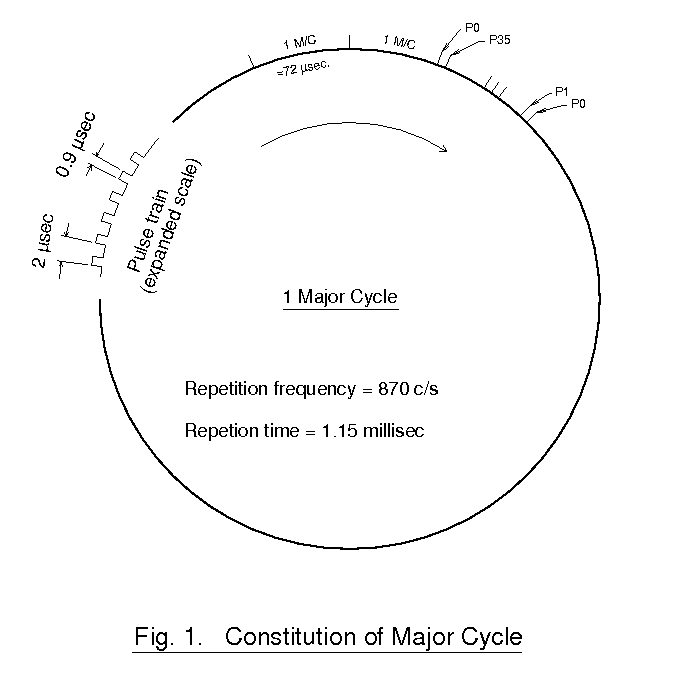
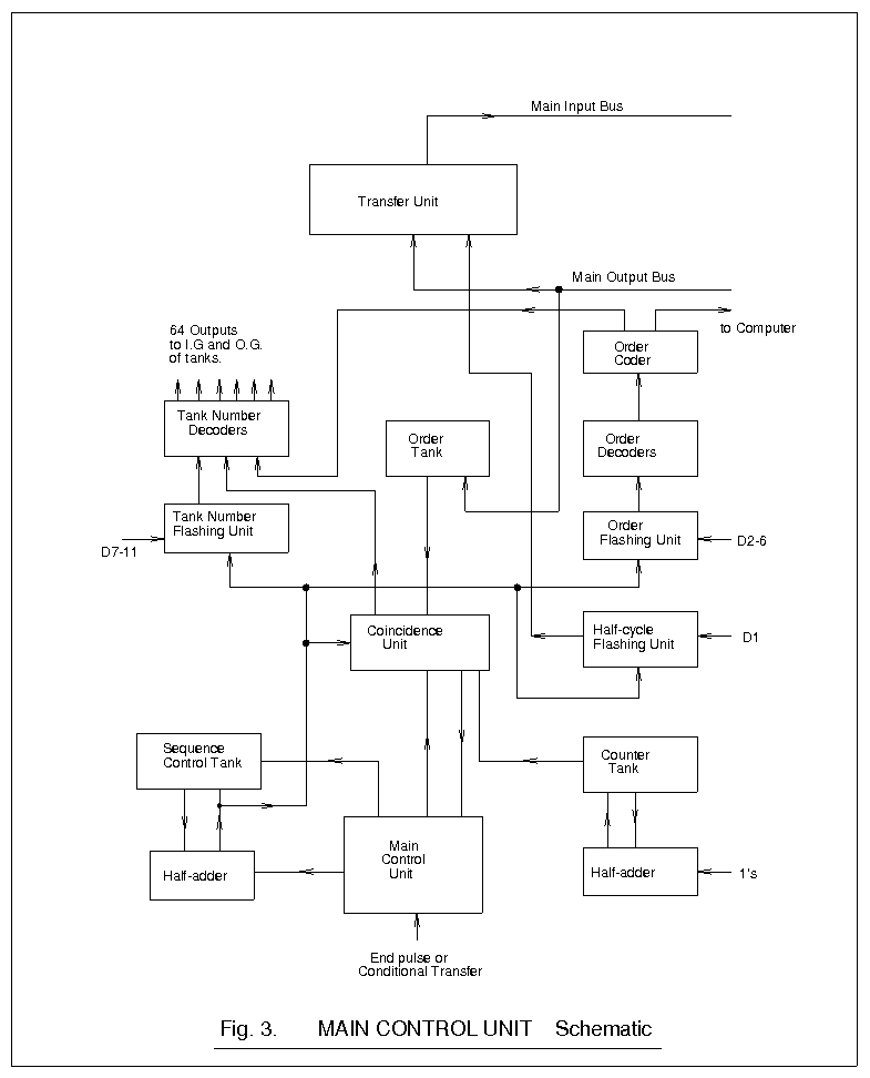
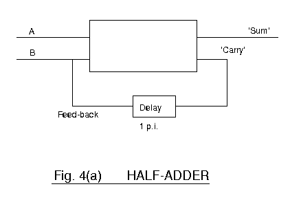
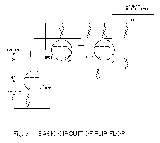
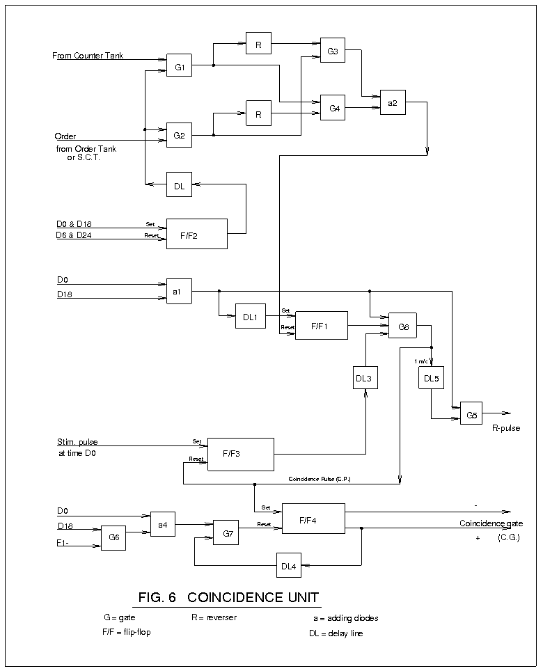
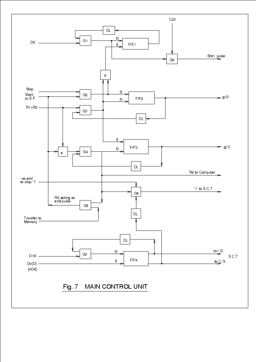
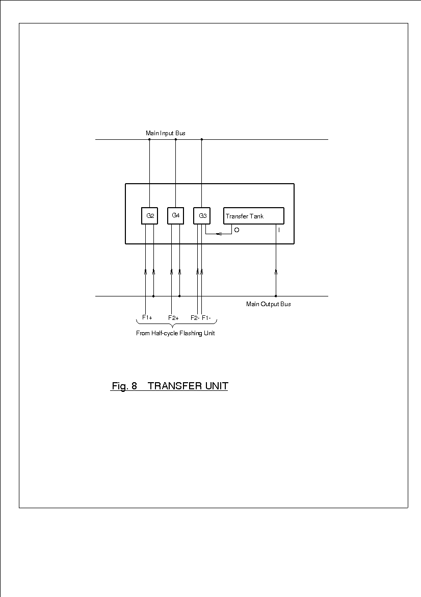
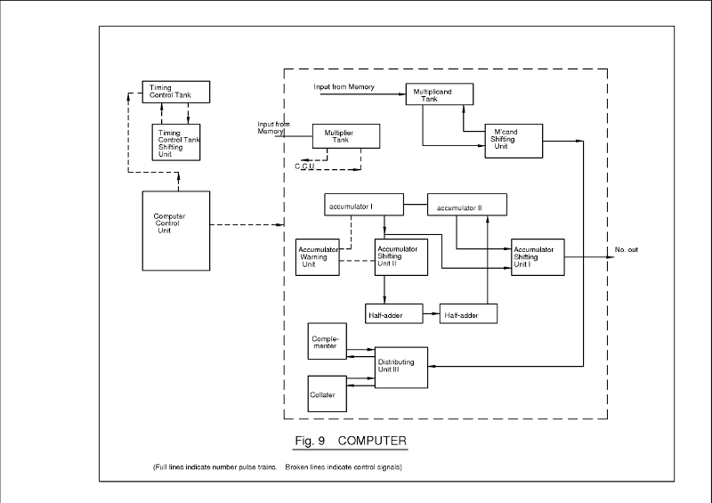
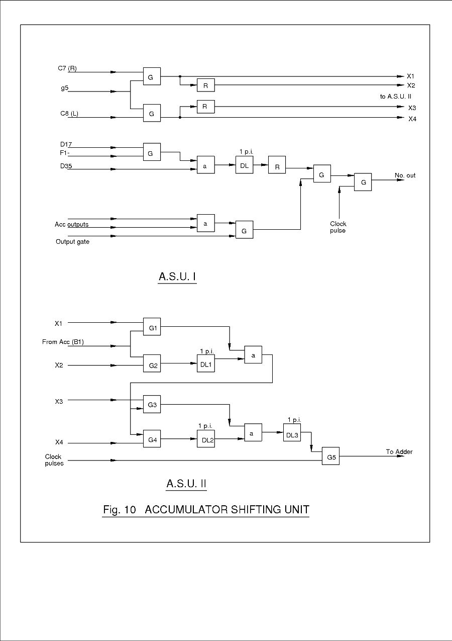
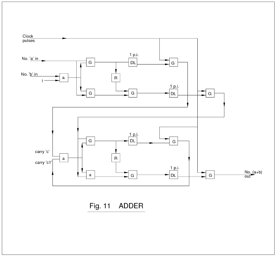
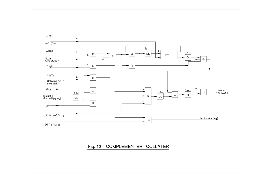
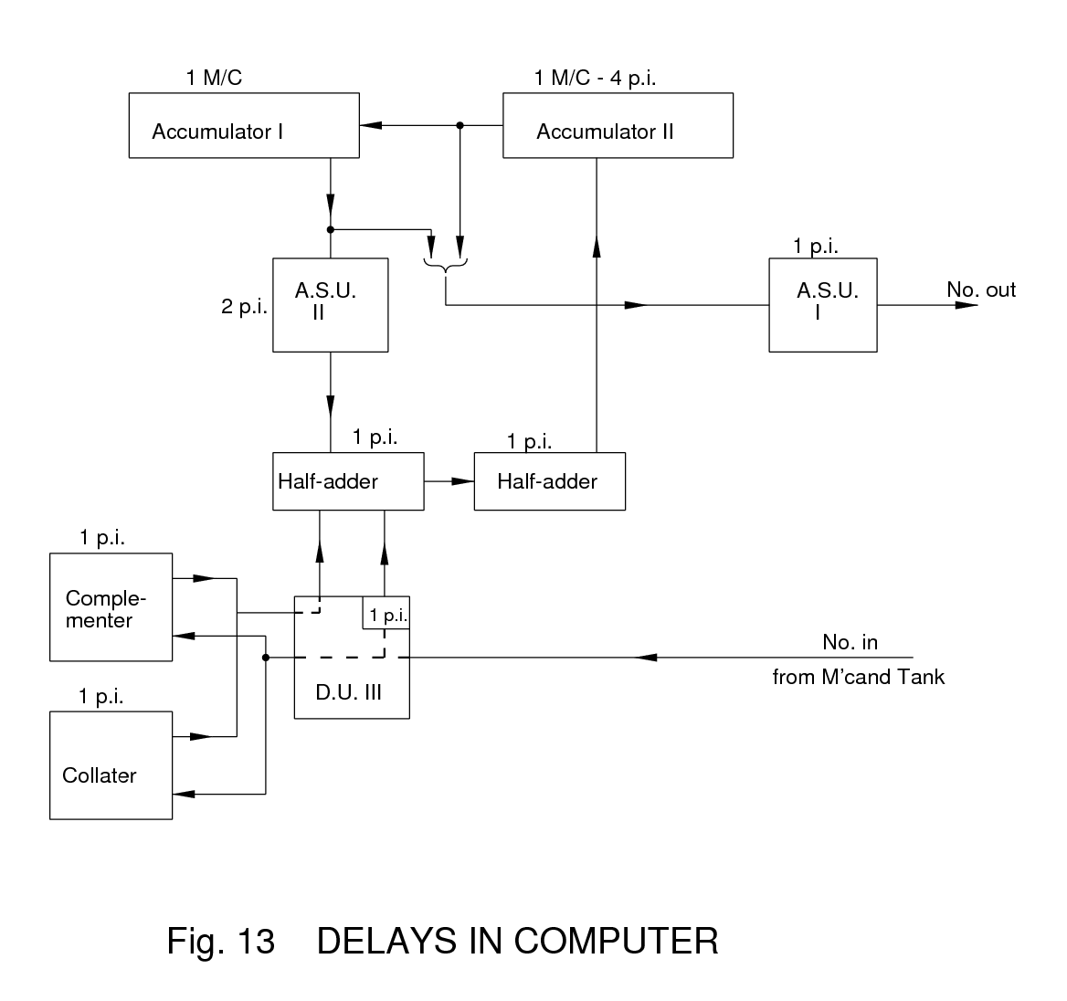