Accumulator Shifting Unit 2
Accumulator
Main Adder
Computer Control I
Computer Control X
Computer Control II
Computer Control III
Computer Control IV
Computer Control V
Computer Control VI
Computer Control VII
Computer Control VIII
Computer Control IX
Coincidence Unit
Clock Generator
Complementer/Collater
Control Switches and Logic
Counter
Digit Pulse Generators
Engineers Control Panel
Frigs
Half Adder Type 1
Half Adder Type 2
Main Control Unit
Multiplicand Tank
Memory Units
Multiplier Tank
Order Coder
Order Decoder 1
Order Decoder 2
Order Flashing Unit
Order Tank
Printer
Sequence Control Tank
Initial Orders Loader
Timing Control Tank
Tank Address Decoder 0
Tank Address Decoder 1
Tank Address Distribution
Tank Address Flashing Units
Tank Address Decoding Final Stage
Tape Reader
Test Frigs
Transfer Unit
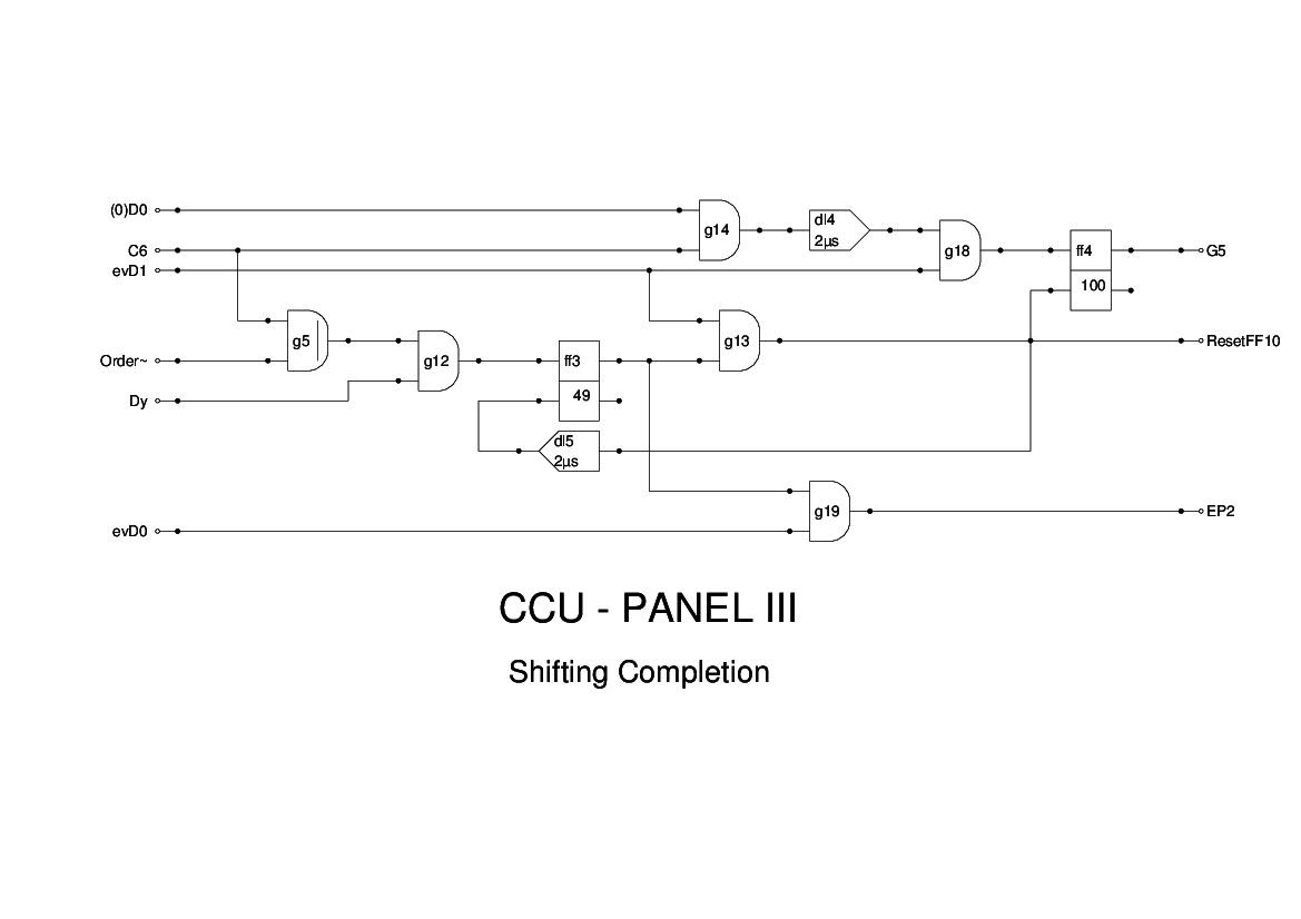
Panel 3 of the CCU is concerned with shift orders. The Edsac shift instructions are strange in that the number of places shifted depends on the position of the least significant bit in the instruction.
The instruction is compared with Dy, which is emitted by the TCT and when there is a match, an end pulse EP2 is generated. This terminates the instruction. For left shifts, the maximum number of places is 13, while for a right shift you can do 15. In these cases, the terminating bit is the least significant bit of the opcode part of the instruction, and the address bits must all be zeros.
The output G5 goes to the Shifting Unit to enable the shifting logic.
The signal ResetFF10 is used to terminate the insertion of propagated sign bits.
The logic here is unchanged from the Report Figure 15, apart from minor adjustments to timing for the simulation.