Accumulator Shifting Unit 2
Accumulator
Main Adder
Computer Control I
Computer Control X
Computer Control II
Computer Control III
Computer Control IV
Computer Control V
Computer Control VI
Computer Control VII
Computer Control VIII
Computer Control IX
Coincidence Unit
Clock Generator
Complementer/Collater
Control Switches and Logic
Counter
Digit Pulse Generators
Engineers Control Panel
Frigs
Half Adder Type 1
Half Adder Type 2
Main Control Unit
Multiplicand Tank
Memory Units
Multiplier Tank
Order Coder
Order Decoder 1
Order Decoder 2
Order Flashing Unit
Order Tank
Printer
Sequence Control Tank
Initial Orders Loader
Timing Control Tank
Tank Address Decoder 0
Tank Address Decoder 1
Tank Address Distribution
Tank Address Flashing Units
Tank Address Decoding Final Stage
Tape Reader
Test Frigs
Transfer Unit
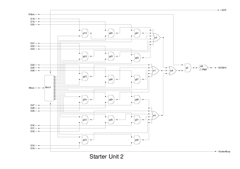
This is the second part of the unit that loads the Initial Orders into memory when the Start button is pressed. I have split the logic into two drawings as it is quite complex. I am not convinced that all this logic was implemented using Valves, some of it may be done using relays as some flipflops need to be active for several seconds while the unit is loading the Initial Orders.
The initial orders are hard-wired onto Uniselectors and provide a pulse train of 17 bits representing the instructions. Each row of the uniselectors gives a separate instruction.
The small square labelled Boot1 is a black-box simulation of the uniselectors and associated logic. This has two inputs and three outputs. The input, IINext,at left signals the unit to request the next word.
At the top of Boot1 is a signal which indicates that the last order has been processed.
At the bottom is a signal which is true while the unit is moving from one word to the next and so the data lines are invalid.
Dow the right side of the unit are 17 data lines representing the 17 bits of each order. These are gated with clock pulses and the result is OR'd together to produce MOB10 which fed to the Main Output Bus for transfer into the main store. It is quite possible that simply wiring the clock pulses to the uniselector wipers and ORing the many contacts together will work. This needs to be thought through and tried.