Accumulator Shifting Unit 2
Accumulator
Main Adder
Computer Control I
Computer Control X
Computer Control II
Computer Control III
Computer Control IV
Computer Control V
Computer Control VI
Computer Control VII
Computer Control VIII
Computer Control IX
Coincidence Unit
Clock Generator
Complementer/Collater
Control Switches and Logic
Counter
Digit Pulse Generators
Engineers Control Panel
Frigs
Half Adder Type 1
Half Adder Type 2
Main Control Unit
Multiplicand Tank
Memory Units
Multiplier Tank
Order Coder
Order Decoder 1
Order Decoder 2
Order Flashing Unit
Order Tank
Printer
Sequence Control Tank
Initial Orders Loader
Timing Control Tank
Tank Address Decoder 0
Tank Address Decoder 1
Tank Address Distribution
Tank Address Flashing Units
Tank Address Decoding Final Stage
Tape Reader
Test Frigs
Transfer Unit
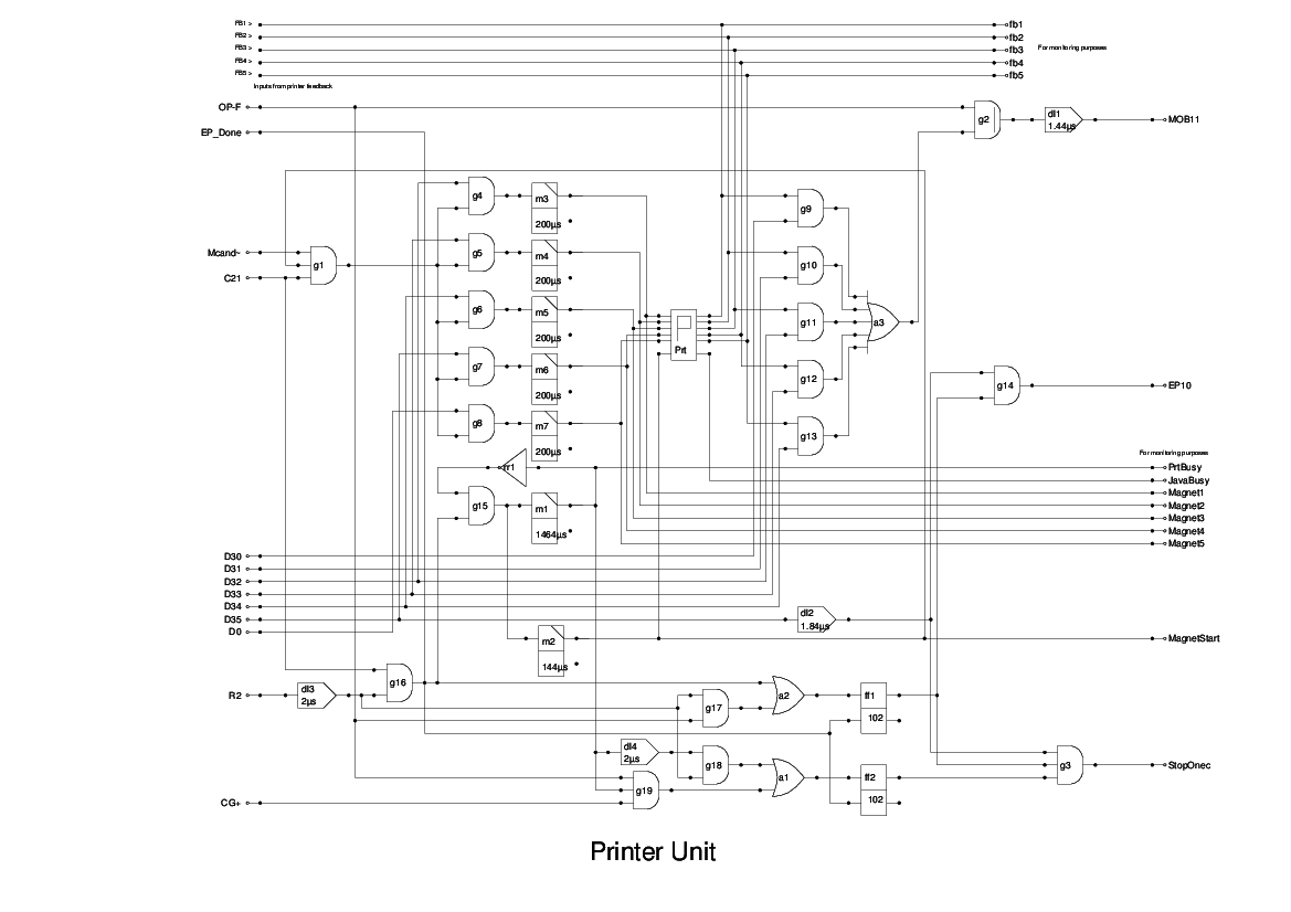
This unit is conjectural. I have devised a 'black box' device for use in the simulation which I believe to be realisable in hardware, but until more details are available as to the physical device used as a printer, this will have to suffice.
There are two instructions relating to the printer, O and F.
In the O instruction, indicated by C21, the output from the Multiplicand Tank is gated into the device. When the data has been read from memory, the pulse R2 is used to signal to the device that the latest data should be printed.
If, at this stage, the printing device is still busy with the previous character, then the busy output will be low and this will prevent the unit from generating an End Pulse (EP10). However, the R2 pulse will have set the flipflop ff1 and this will remain set until the busy line goes up to indicate that the character has been accepted for printing. The next D0 following this will then pass through the gate to provide the End Pulse, and this, in turn, will reset the flipflop.
The F instruction should never need to wait, as the data last sent to the printer is retained and is always immediately available. The printing device continually send this and it is gated onto the MOB when the R2 pulse is signalled.
The receipt of the R2 pulse while the OP-F signal is high sets the flipflop ff2, and the positive output of this gates with the next D0 to produce EP10.
The signal PrtBusy is only provided for monitoring and should simply be a test point.
A major difference between the implementation of this unit and the textual description is the handling of the delay necessary between successive outputs. The Report says that the unit effectively stops the machine until the printer is ready, but there is no logic in the Main Control Unit which can do this. It does say that the data is read repeatedly from the memory until the printer is ready to accept it, and this implies that the Coincidence Unit is repeated stimulated. This is most easily achieved by simply re-scheduling the operation, which is done by suppressing the increment to the SCT.