Accumulator Shifting Unit 2
Accumulator
Main Adder
Computer Control I
Computer Control X
Computer Control II
Computer Control III
Computer Control IV
Computer Control V
Computer Control VI
Computer Control VII
Computer Control VIII
Computer Control IX
Coincidence Unit
Clock Generator
Complementer/Collater
Control Switches and Logic
Counter
Digit Pulse Generators
Engineers Control Panel
Frigs
Half Adder Type 1
Half Adder Type 2
Main Control Unit
Multiplicand Tank
Memory Units
Multiplier Tank
Order Coder
Order Decoder 1
Order Decoder 2
Order Flashing Unit
Order Tank
Printer
Sequence Control Tank
Initial Orders Loader
Timing Control Tank
Tank Address Decoder 0
Tank Address Decoder 1
Tank Address Distribution
Tank Address Flashing Units
Tank Address Decoding Final Stage
Tape Reader
Test Frigs
Transfer Unit
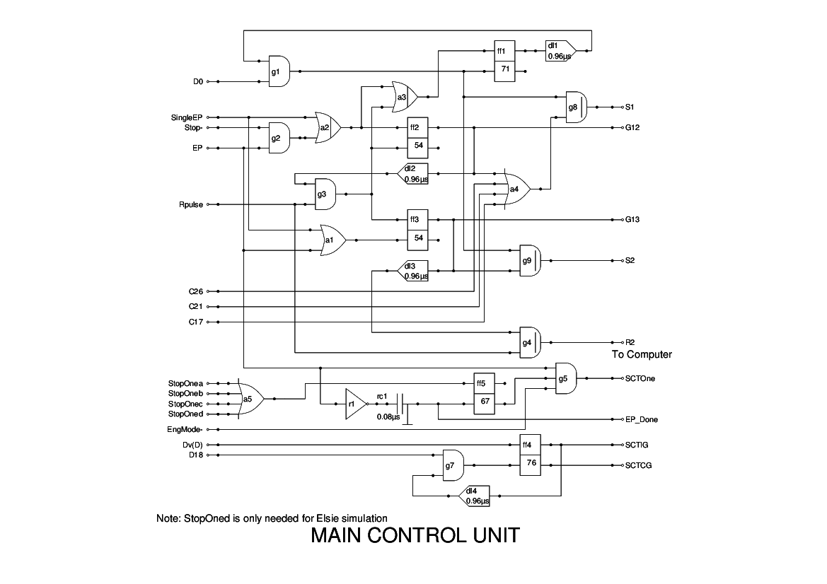
The Main Control Unit (MCU) is the heart of the machine.
This unit controls the sequencing of instructions, and provides control signals to ensure that things happen at the right time.
This has been changed somewhat from the original diagram, which I believe was drawn up before the machine was built. My copy has various pencilled amendments, some of which make sense, others do not. I have therefore gone through several iterations to produce a design which seems to work, though I suspect it may not be the same as that which used in the original machine.
The main pattern of operation is divided into two stages: Stage 1 is essentially what we now call instruction fetch, while Stage 2 is the actual execution of the instruction.
Two flipflops, ff2 and ff3, control these two stages, with outputs g12 signalling Stage 1 and g13 signalling Stage 2. The first is triggered by an End Pulse, EP, or by SingleEP which is essentially a manually operated pulse. Operation can be halted by simply lowering the Stop- signal, which is done by the Halt instruction (Z). This prevents EP from triggering any further Stage 1 phases and so the machine can do nothing until this has been reset and a further EP introduced.
Once Stage 1 has been started, the flipflop ff1 is set and the next D0 triggers the resetting of the flipflop and also produces the signal S1 which acts as a stimulating pulse to the Coincidence Unit. This initiates the search for the next instruction, at the address determined by the Sequence Control Tank.
When the instruction is found, the Coincidence Unit provides a pulse Rpulse which indicates that the instruction has been transferred into the Order Tank. This then resets ff2 and sets ff3, thereby initiating Stage 2. If this is an instruction which will require a memory access, then a further S1 pulse is generated to initiate a search for the data in memory. In any case a stimulating pulse is sent to the Computer Control Unit (CCU) in order to initiate execution of certain instructions.
In the case when a memory access is required, the Rpulse sent by the Coincidence Unit is, in this stage, passed on to the CCU to indicate that the data has been transferred.
Under normal circumstances the CCU will generate an EP pulse to indicate completion. In most cases, this is passed to the SCT to increment the instruction address. In certain cases, however, it is desirable to suppress this increment, and provision is made to gate off this incrmenting pulse. This happens when jumps are made, and when I/O transfers are unable to complete and must be re-scheduled.
Finally, at the bottom of the diagram we have a further flipflop ff4 which allows transfer of the content of the Order Tank to the SCT when a jump is successful. This is set by the pulse Dv(D) and reset by D18.