Accumulator Shifting Unit 2
Accumulator
Main Adder
Computer Control I
Computer Control X
Computer Control II
Computer Control III
Computer Control IV
Computer Control V
Computer Control VI
Computer Control VII
Computer Control VIII
Computer Control IX
Coincidence Unit
Clock Generator
Complementer/Collater
Control Switches and Logic
Counter
Digit Pulse Generators
Engineers Control Panel
Frigs
Half Adder Type 1
Half Adder Type 2
Main Control Unit
Multiplicand Tank
Memory Units
Multiplier Tank
Order Coder
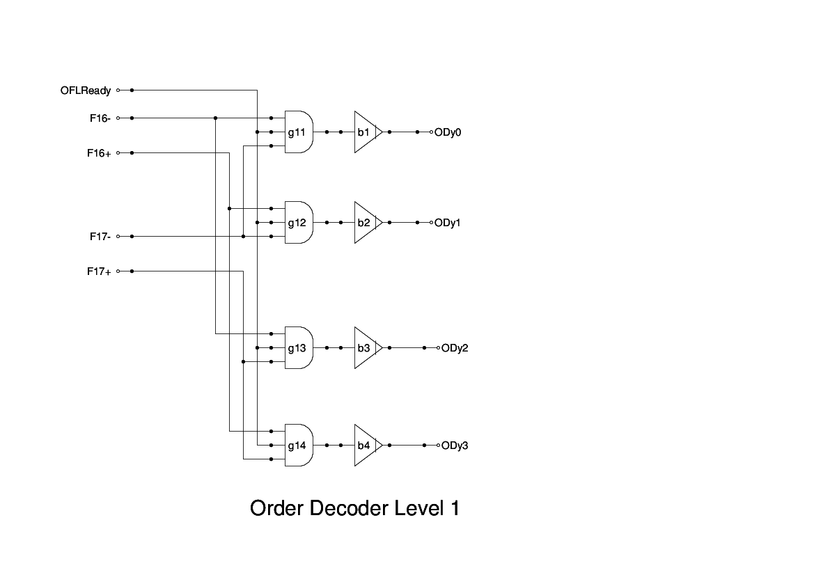
Order Decoder 1
Order Decoder 2
Order Flashing Unit
Order Tank
Printer
Sequence Control Tank
Initial Orders Loader
Timing Control Tank
Tank Address Decoder 0
Tank Address Decoder 1
Tank Address Distribution
Tank Address Flashing Units
Tank Address Decoding Final Stage
Tape Reader
Test Frigs
Transfer Unit
This drawing shows the second level of Order Decoding. Here the signals generated in the first level are gated together to produce the 32 possible combinations of the five function digits.
The outputs from the second level gates are routed directly to the Order Coder Unit.
The second level gates are numbered using the octal notation for the bit pattern that they decode.
It is not clear if all of the signals are needed - my simulation has assumed that they are, as there are hints that an invalid opcode will cause the machine to halt. My simulation provides an explicit action for a halt, but this may not be needed as the machine will simply cycle on the current instruction if it is not a legal one. No end pulse will be generated and so the MCU will never move to the next instruction.