Accumulator Shifting Unit 2
Accumulator
Main Adder
Computer Control I
Computer Control X
Computer Control II
Computer Control III
Computer Control IV
Computer Control V
Computer Control VI
Computer Control VII
Computer Control VIII
Computer Control IX
Coincidence Unit
Clock Generator
Complementer/Collater
Control Switches and Logic
Counter
Digit Pulse Generators
Engineers Control Panel
Frigs
Half Adder Type 1
Half Adder Type 2
Main Control Unit
Multiplicand Tank
Memory Units
Multiplier Tank
Order Coder
Order Decoder 1
Order Decoder 2
Order Flashing Unit
Order Tank
Printer
Sequence Control Tank
Initial Orders Loader
Timing Control Tank
Tank Address Decoder 0
Tank Address Decoder 1
Tank Address Distribution
Tank Address Flashing Units
Tank Address Decoding Final Stage
Tape Reader
Test Frigs
Transfer Unit
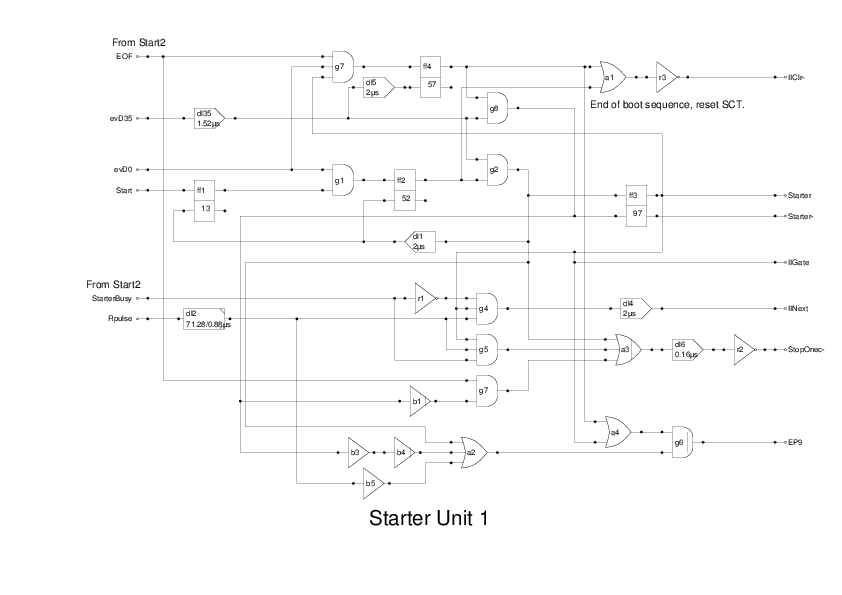
This is the part of the unit that loads the Initial Orders into memory when the Start button is pressed. I have split the logic into two drawings as it is quite complex. I am not convinced that all this logic was implemented using Valves, some of it may be done using relays as some flipflops need to be active for several seconds while the unit is loading the Initial Orders.
This section acts as controller and generates signals to keep the MCU in the correct state to load the Orders.
The Start pulse is generated when the operator presses the start button. This ensures that the uniselectors are in the home position, and are presenting the bit stream for the first instruction, by raising the resetinput.
The Starter Busy signal from the Start2 module is a busy line, and this acts to inhibit the normal increment of the SCT when the end pulse (EP9) is signalled. The result is that the Main Control Unit simply restarts the sequence, and the data stream from the device gets written to store at the next coincidence. This continues until the busy line is raised, indicating that the next instruction has been written to store, and so the SCT can be incremented to allow the MCU to process the next instruction.
The EOF signal is an end signal to indicate that the last instruction has been processed. This resets flip-flop ff4 which drops the IIClr- output. This in turn closes the recirculating path in the SCT, thereby setting it back to zero in readiness for the first true instruction fetch to take place.
The Report gives only a vague description of this unit, with no logic diagram. It has therefore been re-invented by me in order to achieve the desired effect. It works under simulation, and is the best I can do without further information.
One problem which needs to be resolved is that the flipflops used in the original machine are essentially monostable and will revert to the initial state after some period of time. I expect the operation of loading the Initial Instructions will take over a second, so the flipflops need either a very long time constant, or to be modified into true bistables. Using a bistable would give the added advantage of providing the negative output without additional inverters, required if the original circuit is employed.