Accumulator Shifting Unit 2
Accumulator
Main Adder
Computer Control I
Computer Control X
Computer Control II
Computer Control III
Computer Control IV
Computer Control V
Computer Control VI
Computer Control VII
Computer Control VIII
Computer Control IX
Coincidence Unit
Clock Generator
Complementer/Collater
Control Switches and Logic
Counter
Digit Pulse Generators
Engineers Control Panel
Frigs
Half Adder Type 1
Half Adder Type 2
Main Control Unit
Multiplicand Tank
Memory Units
Multiplier Tank
Order Coder
Order Decoder 1
Order Decoder 2
Order Flashing Unit
Order Tank
Printer
Sequence Control Tank
Initial Orders Loader
Timing Control Tank
Tank Address Decoder 0
Tank Address Decoder 1
Tank Address Distribution
Tank Address Flashing Units
Tank Address Decoding Final Stage
Tape Reader
Test Frigs
Transfer Unit
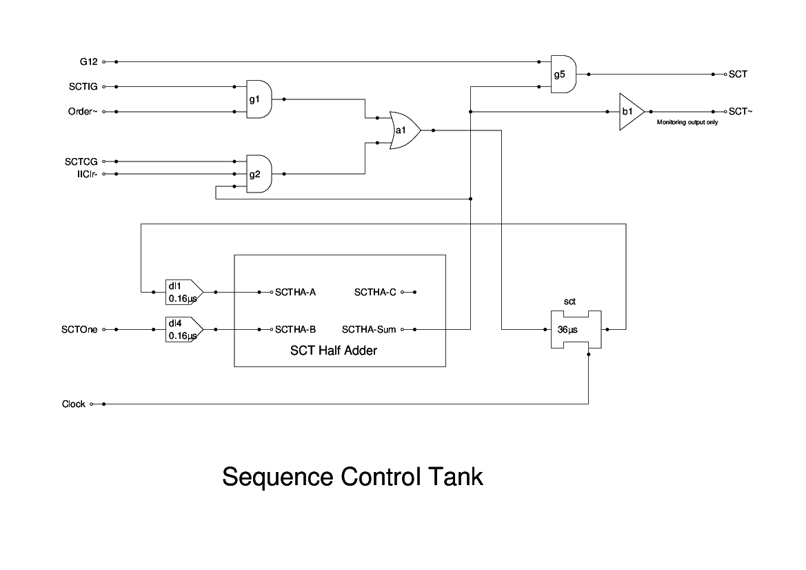
The SCT is another short (18 bit) mercury tank. It contains the current instruction address. The surrounding logic includes a half-adder so that the increment pulses SCTOne can be added to the current value on receipt of an End Pulse EP.
The output from the tank is gated out as Order during Stage 1 processing. This goes to the Coincidence Unit to select the current instruction from the memory.
At the beginning and end of the startup, the signal IIClr- falls to close off the recirculation and set the SCT to zero.
During conditional jumps, when the test is true, then the MCU will raise the SCTIG signal, and lowers the SCTCG signal. This enable the contents of the Order Tank to be gated in to replace the existing value.
The signal SCT~ is provided for monitoring the simulation. It should be implemented as a test point only.
This unit is another case where we have had to devise the logic based on a brief textual description. The only problems were in ensuring that the timings are correct.