Accumulator Shifting Unit 2
Accumulator
Main Adder
Computer Control I
Computer Control X
Computer Control II
Computer Control III
Computer Control IV
Computer Control V
Computer Control VI
Computer Control VII
Computer Control VIII
Computer Control IX
Coincidence Unit
Clock Generator
Complementer/Collater
Control Switches and Logic
Counter
Digit Pulse Generators
Engineers Control Panel
Frigs
Half Adder Type 1
Half Adder Type 2
Main Control Unit
Multiplicand Tank
Memory Units
Multiplier Tank
Order Coder
Order Decoder 1
Order Decoder 2
Order Flashing Unit
Order Tank
Printer
Sequence Control Tank
Initial Orders Loader
Timing Control Tank
Tank Address Decoder 0
Tank Address Decoder 1
Tank Address Distribution
Tank Address Flashing Units
Tank Address Decoding Final Stage
Tape Reader
Test Frigs
Transfer Unit
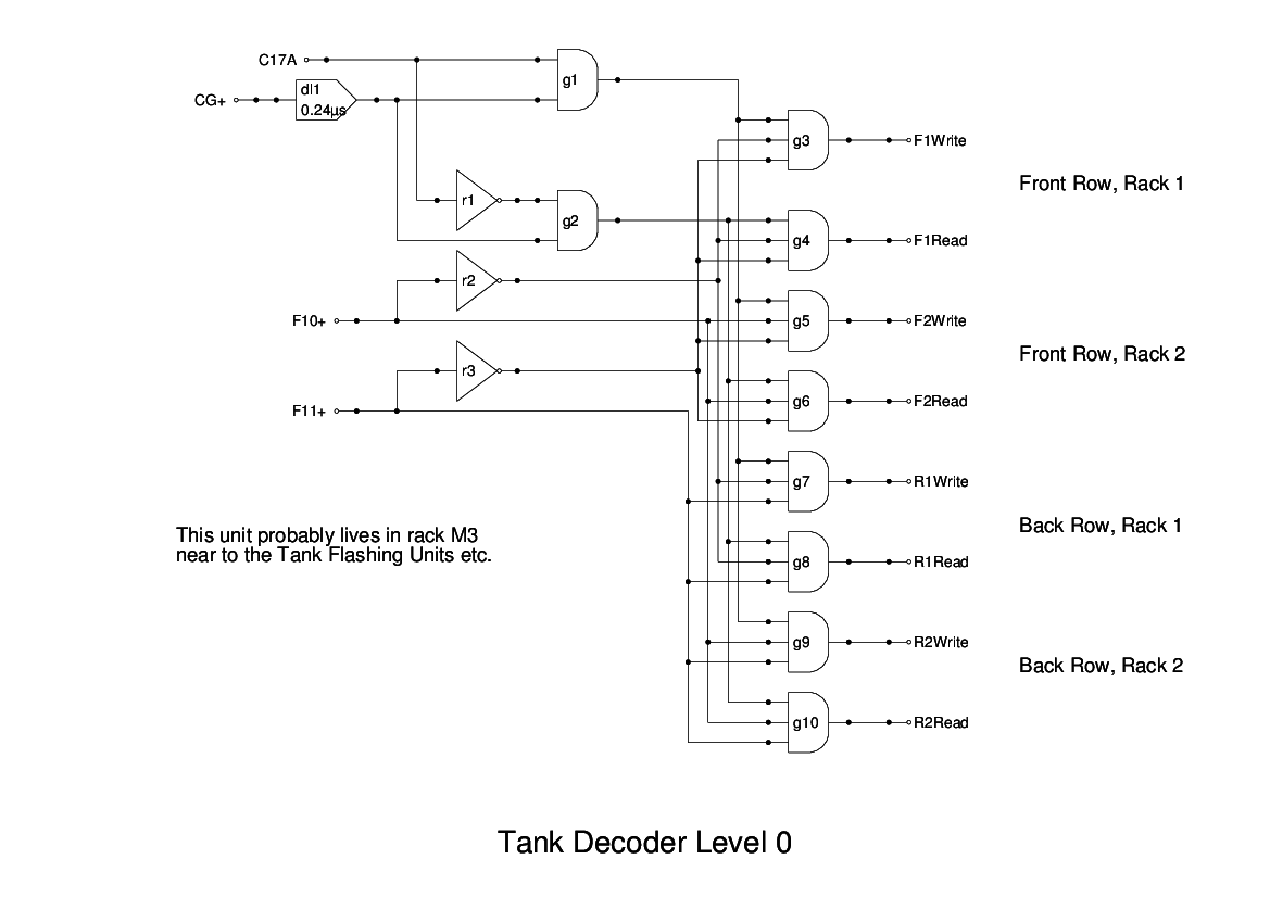
The Tank Number Decoder is used to select the memory tank to be accessed, based on bits 7 - 11 of the Tank Flashing Unit.
The report provides a textual description but no diagrams. Initially I chose to implement this unit using 4-input and gates, but this has been revised after further study of photographs of the panels which we believe performed these functions.
The Memory Access modules are replicated over four racks, with two in the fron row and two in the back row. The first level of decoding uses the two most significant bits of the tank number field (bits 10 and 11) to determine which rack should be selected. It is not clear where this logic is located, but somewhere near the Order Flashing Units would seem sensible.
The two bits of the tank number (10 and 11), are gated with the coincidence gate CG+ and C17 and its inverse. This latter determines if the access is a read from or a write to memory. The gates provide control signals to the individual racks for further decoding.