Accumulator Shifting Unit 2
Accumulator
Main Adder
Computer Control I
Computer Control X
Computer Control II
Computer Control III
Computer Control IV
Computer Control V
Computer Control VI
Computer Control VII
Computer Control VIII
Computer Control IX
Coincidence Unit
Clock Generator
Complementer/Collater
Control Switches and Logic
Counter
Digit Pulse Generators
Engineers Control Panel
Frigs
Half Adder Type 1
Half Adder Type 2
Main Control Unit
Multiplicand Tank
Memory Units
Multiplier Tank
Order Coder
Order Decoder 1
Order Decoder 2
Order Flashing Unit
Order Tank
Printer
Sequence Control Tank
Initial Orders Loader
Timing Control Tank
Tank Address Decoder 0
Tank Address Decoder 1
Tank Address Distribution
Tank Address Flashing Units
Tank Address Decoding Final Stage
Tape Reader
Test Frigs
Transfer Unit
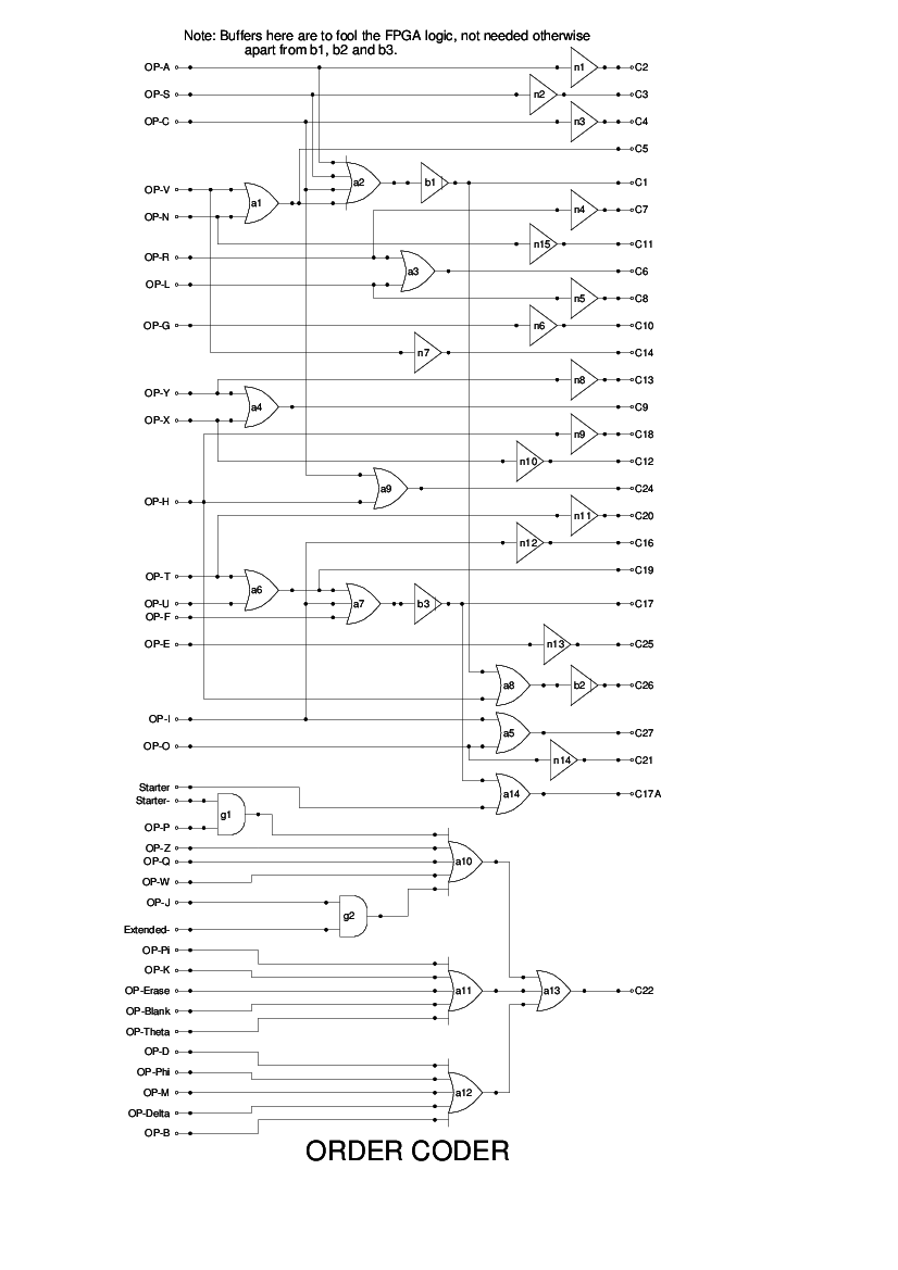
The Order Coder is a collection of OR gates which simply combine one or more of the individual instructions to simplify logic elsewhere. In some cases no gate is involved and the logic is simply a renaming of the signal. In other cases, up to 7 inputs may be combined (C26).
The signal OP-P is not strictly a valid instruction. However, it is produced during the instruction fetch phase of the MCU, and is treated as one of the instructions that read data (in this case the instruction) from memory.
No logic diagram for the Order Coder is given in the Report, the text simply says that it is a collection of adding diodes and cathode followers. The above is therefore a simple interpretation of this; it is difficult to see how it could have been otherwise.