Accumulator Shifting Unit 2
Accumulator
Main Adder
Computer Control I
Computer Control X
Computer Control II
Computer Control III
Computer Control IV
Computer Control V
Computer Control VI
Computer Control VII
Computer Control VIII
Computer Control IX
Coincidence Unit
Clock Generator
Complementer/Collater
Control Switches and Logic
Counter
Digit Pulse Generators
Engineers Control Panel
Frigs
Half Adder Type 1
Half Adder Type 2
Main Control Unit
Multiplicand Tank
Memory Units
Multiplier Tank
Order Coder
Order Decoder 1
Order Decoder 2
Order Flashing Unit
Order Tank
Printer
Sequence Control Tank
Initial Orders Loader
Timing Control Tank
Tank Address Decoder 0
Tank Address Decoder 1
Tank Address Distribution
Tank Address Flashing Units
Tank Address Decoding Final Stage
Tape Reader
Test Frigs
Transfer Unit
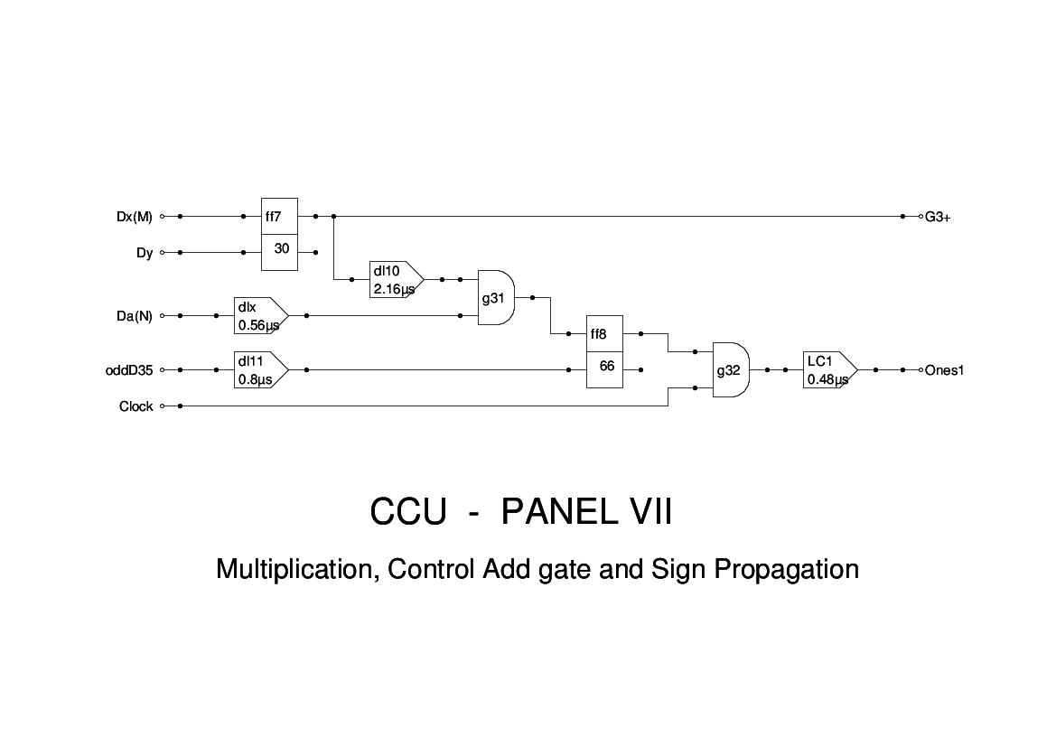
Panel 7 of the CCU is a further part of the multiplication logic.
The signal Dx(M) is raised whenever the bit corresponding to the current position of Dx is set in the Multiplier Tank. This sets FF7 whose positive output is G3+ which controls the output from the Multiplicand Tank to the Adder. The flipflop is reset by the Dy pulse. The negative output of this flipflop, G3-, does not appear to be needed and can be omitted.
In addition the signal Da(N) indicates that the multiplicand is negative, and enables the addition of ones until reset by evD0.
The logic of this panel follows that of Figure 15, apart from timing issues.