Accumulator Shifting Unit 2
Accumulator
Main Adder
Computer Control I
Computer Control X
Computer Control II
Computer Control III
Computer Control IV
Computer Control V
Computer Control VI
Computer Control VII
Computer Control VIII
Computer Control IX
Coincidence Unit
Clock Generator
Complementer/Collater
Control Switches and Logic
Counter
Digit Pulse Generators
Engineers Control Panel
Frigs
Half Adder Type 1
Half Adder Type 2
Main Control Unit
Multiplicand Tank
Memory Units
Multiplier Tank
Order Coder
Order Decoder 1
Order Decoder 2
Order Flashing Unit
Order Tank
Printer
Sequence Control Tank
Initial Orders Loader
Timing Control Tank
Tank Address Decoder 0
Tank Address Decoder 1
Tank Address Distribution
Tank Address Flashing Units
Tank Address Decoding Final Stage
Tape Reader
Test Frigs
Transfer Unit
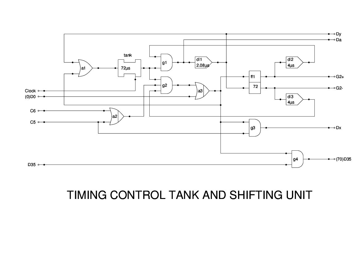
The Timing Control Tank is a full-word mercury delay line which is used to maintain a timing pulse for use in multiplication.
The initial pulse comes in as (0)D0 and is generated in CCU Panel 2 from evD0. During the multiplication instruction and shift instructions, the pulse recirculates alternately via two feedback paths, one of which introduces a 1PI delay. Thus, every two MCs the pulse is delayed to arrive 1PI later. This is achieved by means of a flipflop ff1, which control the feedback gates, and other gates on its own inputs. The flipflop therefore toggles between the two states.
In a shift instruction, this process terminates when the instruction detects a coincidence between the timing pulse Dy and the current instruction. In the case of multiplication it proceeds until the timing pulse has tested all 36 bits of the multiplier, i.e. 72 MCs.
Two main outputs are provided from the unit: Dx marks the start of each cycle, and Dy appears 1MC later marking the end of the phase. Dx is used in the CCU to open the gate which admits the Multiplicand to the Adder, and Dy closes it.
Further outputs are G2+ and G2- which control the shifting in the Multiplicand, (70)D0 which signals to the CCU that the final addition (or subtraction) is about to be made, and Da which is used to test the sign of the Multiplicand, so that trailing ones can be added.
This unit is illustrated in the Report as Figure 14. However, some small changes were found to be necessary. The gating input to g2 in the original is just C5, but the tank needs to operate for shift instructions as well as multiplication, so I have ORed C5 with C6. Also, no provision is shown in Figure 14 for the insertion of the initial pulse, (0)D0 which is generated in CCU Panel 2. I have ORed this in with the output of g2. The output in Figure 14 labelled as Du I have renamed Da for consistency. Finally, the tank itself is included here although it is, of course, a separate unit.