Accumulator Shifting Unit 2
Accumulator
Main Adder
Computer Control I
Computer Control X
Computer Control II
Computer Control III
Computer Control IV
Computer Control V
Computer Control VI
Computer Control VII
Computer Control VIII
Computer Control IX
Coincidence Unit
Clock Generator
Complementer/Collater
Control Switches and Logic
Counter
Digit Pulse Generators
Engineers Control Panel
Frigs
Half Adder Type 1
Half Adder Type 2
Main Control Unit
Multiplicand Tank
Memory Units
Multiplier Tank
Order Coder
Order Decoder 1
Order Decoder 2
Order Flashing Unit
Order Tank
Printer
Sequence Control Tank
Initial Orders Loader
Timing Control Tank
Tank Address Decoder 0
Tank Address Decoder 1
Tank Address Distribution
Tank Address Flashing Units
Tank Address Decoding Final Stage
Tape Reader
Test Frigs
Transfer Unit
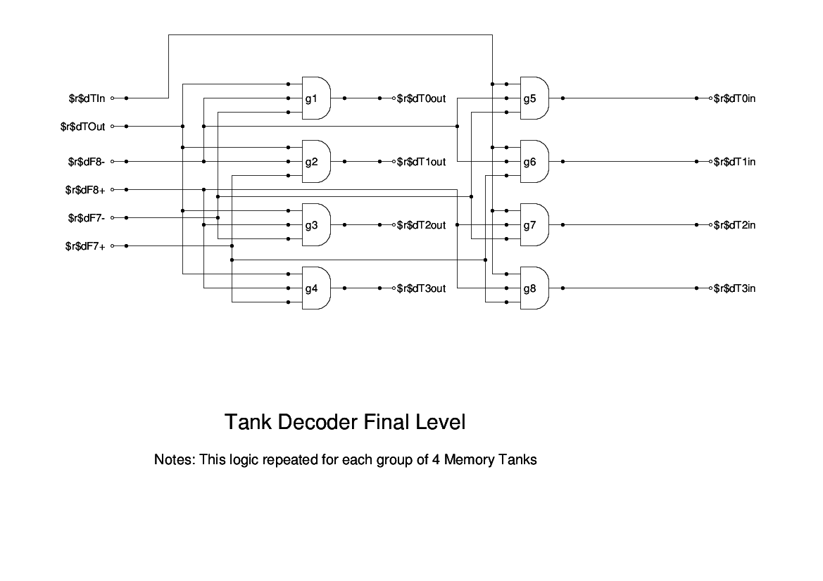
This drawing shows the final level of decoding, which is duplicated on each of the memory racks, one panel handling the upper tanks and the other handling the lower tanks.
At the left side of the drawing we see four 3-input AND gates which take two of the final tank address bits (or their inverses) along with the TUpOut signal to produce the signals which open the output gate on the selected Memory Unit when memory is being read.
At the right side, a similar group takes the same selection bits and gates them with TUpIn to provide the signals to open the input gates, and also, via the inverters in the Distribution Units, close off the recirculation path.
Note that the drawing shows only the Upper Final level decoder, the lower one uses TDownIn and TDownOut.
Please ignore the four signals marked T4In-,T5In-,T6In-, and T7In-. They are just there to keep the simulation happy!