Accumulator Shifting Unit 2
Accumulator
Main Adder
Computer Control I
Computer Control X
Computer Control II
Computer Control III
Computer Control IV
Computer Control V
Computer Control VI
Computer Control VII
Computer Control VIII
Computer Control IX
Coincidence Unit
Clock Generator
Complementer/Collater
Control Switches and Logic
Counter
Digit Pulse Generators
Engineers Control Panel
Frigs
Half Adder Type 1
Half Adder Type 2
Main Control Unit
Multiplicand Tank
Memory Units
Multiplier Tank
Order Coder
Order Decoder 1
Order Decoder 2
Order Flashing Unit
Order Tank
Printer
Sequence Control Tank
Initial Orders Loader
Timing Control Tank
Tank Address Decoder 0
Tank Address Decoder 1
Tank Address Distribution
Tank Address Flashing Units
Tank Address Decoding Final Stage
Tape Reader
Test Frigs
Transfer Unit
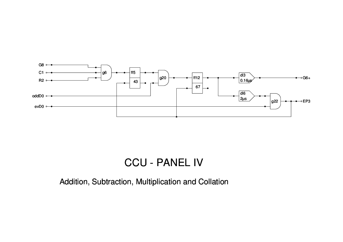
Panel 4 of the CCU is concerned with Add, Subtract and Collate instructions. The control signal C1 comes up for these, and also for the multiplication instructions. However, by the time the R2 pulse comes in, if the instruction was a multiply with a non-zero multiplicand, then the signal G8 will have been dropped by CCU2.
On the other hand, if a multiply with a zero multiplicand has been issued, then CCU2 will not have been triggered and G8 will still be high. This then causes this panel to treat it as an addition of zero, thereby shortening the instruction time considerably.
I don't understand the use of Dt and Dt(A). The report says these are needed to test the sign of the Multiplicand. If Dt(A) indicates a negative number being added, then an additional sign pulse is added.
Since addition requires only single length arithmetic, the gating signal G6+ is raised by oddD0 and reset by the following evD0. This signal controls the output from the multiplicand. The inverted signal G6- appears not to be required.
The evD0 which closes the gate also acts as the End Pulse (EP3).
This diagram corresponds with that of Figure 15 of the Report, apart from the delay elements which have been inserted to adjust signal timings.